Haven't thought of that one either. Very good idea and offsetting the linestrings is the best solution since it keeps everything perpendicular to each string.
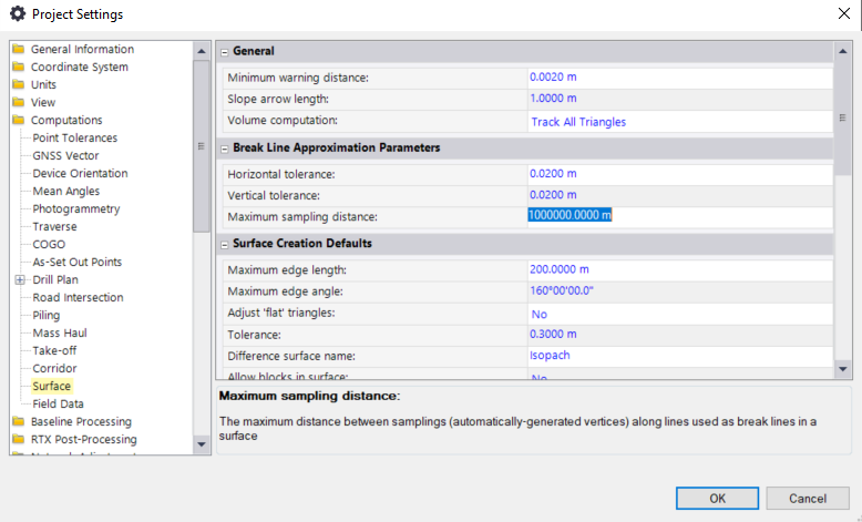
You might want to go into the project settings and lower the Maximum Sampling Distance. That way you can create additional nodes on straight segments and hence additional triangles in your surfaces. The denser those surfaces are the more accurate the intersection linestring will be.
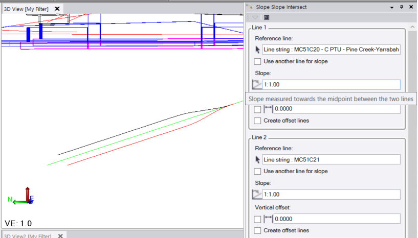
Since offsetting the lines is the best solution you can also try the Slope-Slope-Intersect Macro, that should have been installed with TBC. I don't know how it computes internally, if it keeps everything perpendicular to each string, you might want to compare the result to the DTM-Intersect-Solution. A quick compare with my two simple strings shows differences in the 5th decimal, so nearly nothing.
Important for both is to create a copy of the alignments and change the heights to a uniform level.
------------------------------
Ronny Schneider
------------------------------
Original Message:
Sent: 05-17-2022 07:23
From: Robert Barton
Subject: Create Centerline between two alignments
Set both alignments to elevation 1.00, offset each alignment 100' and vertically 1' across each other. For instance NB offset 100' *west and SB 100' *east. make surfaces out of the NB and its offset and the SB and its offset. Run the surface intersection and they will intersect in the middle.
------------------------------
Robert Barton
Original Message:
Sent: 05-13-2022 12:47
From: sean maxwell
Subject: Create Centerline between two alignments
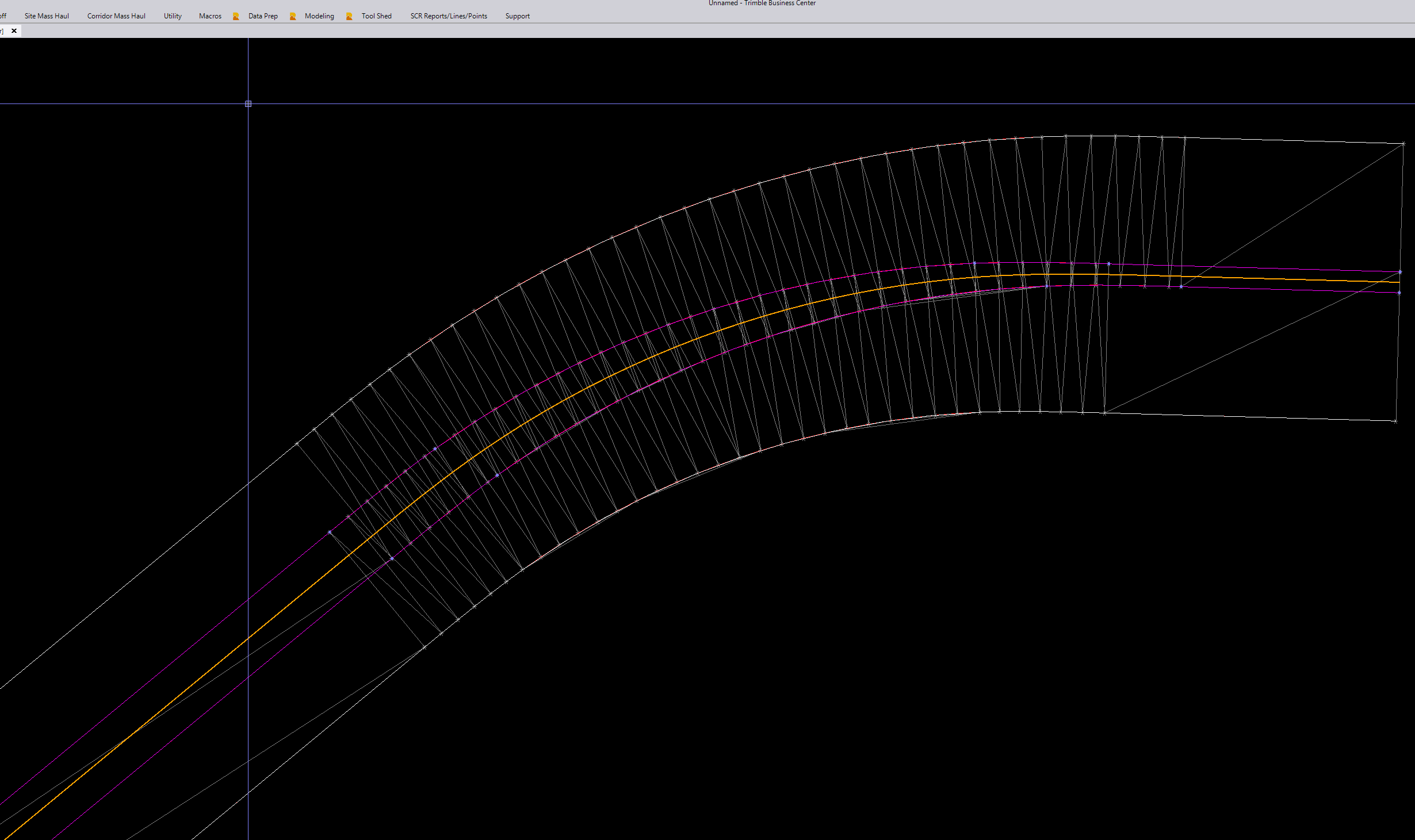
Please see attached photo. The two white lines are centerline alignments of northbound and southbound railways. I am trying to get a line created directly in the middle of the two. The line doesnt need vertical elements, only horizontal. THe only way i can think to do it is manually draw perpendicular lines between the two and select the midpoint. But wondering if there is an easier more accurate solution. Of course the alignments vary in width from eachother and have spiral curves in and out with different start locations so its not as simple as offsetting one of the lines.
Thanks
------------------------------
sean maxwell
------------------------------