My experience with CAD Cross Sections is that it is all about "Data Prep" making sure that you get the data clean and set up on layers so that you set yourself up for success. Hoping that the CAD Data straight after import is clean enough to just work is wishful thinking in 80% of cases. In this example there were a few issues that dictate which method of conversion to use. As with many data sets, they highlight some kind of "corner case" that makes me run to development to discuss the issue, however in order to get you going as users, we try to find a work around to the issue so that at least you can get your job done. So there is a "corner case" in this example that we are still looking at, however here is the work process to use to convert the data.
In this example the CAD Cross Sections Look Like This
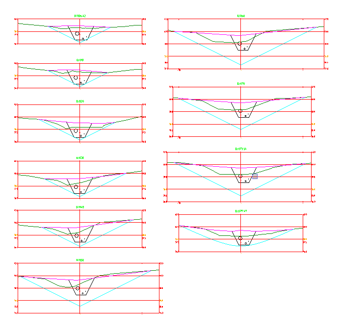
If you look closer at some of the sections they look like this

And some look like this

The difference is in the Offset Axis - note the lower of the two has a pair of offset labels, yet the first doesn't. This is the main challenge in this particular example. In the second section we could determine Horizontal Scale but in the first section there is no indicator of scale (and that is also the first section type we see - so we would use the values of 36 as the offsets (as they are close to the Grid lines (within the tolerance specified) and because there are no other labels we would select those incorrectly - this would make the sections 72 meters wide and not 20m wide as per the design.
The second issue is all of the little Tick Marks - if selected as Grid Lines - they would duplicate in some cases and in others create new but very short grid lines - this can also be an issue in some cases
The third issue is that when you looked at the 0 offset label, they were all duplicated on the same layer - duplicate data - whether it be labels, grids, station labels etc all create a degree of ambiguity in the process, so spend time cleaning that up. Same for the section profiles - make sure that they are joined correctly and that they have only one instance of each profile.
Spend time getting the data clean and on layers that you know and understand. You will need the following sorted out by layer to make this easy
- Grid Lines you want to use
- Grid Labels you want to use
- Station Labels you want to use
- Each Surface Type Section Collection that you want to Convert
You will also want Target Layers for the Stored Cross Sections that you are going to create. This could be the same as the source layer for each of the surface section profiles.
In this example I elected to set the cross sections up as follows for conversion

Because there was no Horizontal Scale I chose this method of setup, and then in execution of the conversion I used the No Grid Method (which requires entry of a Horizontal and Vertical Scale parameter), and requires at least a Datum Line and a 0 offset grid line to work with. This approach works well for No scale or limited scale sections.
The following video shows how to do each surface profile as a set and as individual elements.
Hope that this helps you to better understand the nuances of converting CAD Cross Sections.
Alan