Good morning TBC’ers! Have you ever been preparing a plan set, such as an alignment or curb lines, for field staking and wished you could join lines and arcs with tangent arcs of a specific radius? Or have you wanted to join line work to create a sloped transition? Well, today I will be demonstrating how to create a fillet or chamfer line segment for two non-parallel line or arc segments with the CAD Command Line.
A fillet is a tangent arc at the intersection of two non-parallel line segments, creating a rounded corner. A fillet line segment requires two specified line/ arc segments and a specified radius:

A chamfer is a straight segment across the intersection of two non-parallel line segments, beveling a corner. A chamfer line segment requires two specified line/ arc segments and either one distance(1), two distances (2), or a distance and an angle (3):

To fillet using the CAD Command Line, follow these steps:
1. Press [F3] to open the CAD Command Line.
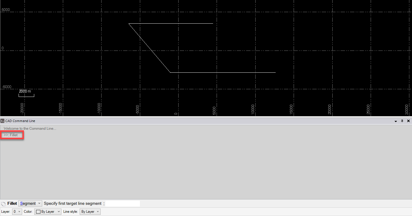
2. Type f or F at the command prompt, and press [Enter]:
3. Skip the Layer, Color, and Line style lists below the command prompt; they do not apply to this operation.
4. Based on the Segment target type highlighted at the prompt, pick the first line segment in a supported view (Plan, Sheet, or Cutting Plane), or type a keyword character to use another mode. The options are:
A. Segment - Type S to fillet just selected segments. Then pick the second segment in the view.
B. Entireline - Type E to fillet an entire selected line. Then pick the line.

In this demonstration, I chose to fillet selected segments:

5. If needed, enter T to toggle Trim off to retain parts of the segment beyond the fillet. Otherwise, those parts will be removed. The command remembers your selection the next time you run the operation.
6. Enter a radius or pick two points in the view to specify the radius. The corner is filleted. If the selected segments do not cross planimetrically, the arc connects the segment end points in 3D. The command remembers the specified radius used the next time you run the operation.

7. Continue to pick pairs of line segments to fillet using the same radius. A preview of the fillet that would be created based on the last selection is shown as you work.
8. Press[Escape] to close the command, and press [Spacebar] to rerun the command.
To chamfer using the CAD Command Line, follow these steps:
1. Press [F3] to open the CAD Command Line.
2. Typecha or CHA at the command prompt, and press [Enter]:

3. Skip the Layer, Color, and Line style lists below the command prompt; they do not apply to this operation.
4. Based on the Segment target type highlighted at the prompt, pick the first line segment in a supported view (Plan, Sheet, or Cutting Plane), or type a keyword character to use another mode. The options are:
A. Segment - Type S to chamfer just selected segments. Then pick the second segment in the view.
B.Entire line - Type E to chamfer an entire selected line. Then pick the line.

In this demonstration, I chose to chamfer selected segments:

5. If needed, enter T to toggle Trim off to retain parts of the segment beyond the fillet. Otherwise, those parts will be removed. The command remembers your selection the next time you run the operation.
6. Based on the One Distance mode highlighted at the prompt, enter a length for the chamfer segment, or enter a keyword character to use another mode. The options are:
- One distance - Enter O and then the distance from the corner at which you want the new chamfer segment to begin (or pick two points in the view to specify the distance). The command remembers the last distance used the next time you run the operation.
- Two distances - Enter W and then the distance from the corner at which you want the chamfer to start on the first segment. Then enter the distance from the corner at which you want the chamfer to start on the second segment. Alternatively, you can pick two points in the view to specify each distance.
- Distance with Angle - Enter A and then the distance from the corner at which you want the chamfer to start on the first segment. Then enter the angle from the first segment at which you want the chamfer to start on the second segment.

For this demonstration, I entered two distances. The chamfer is created. If lines do not cross planimetrically, the chamfer line connects the segment end points in 3D.

7. Continue to pick pairs of segments to chamfer using the same modes. A preview of the chamfer that would be created based on the last selection is shown as you work.
8. Press[Escape] to close the command, and press [Spacebar] to rerun the command.
I hope this tip comes in handy next time you are preparing a plan set in TBC!