Measurement on scanned material for digitizing boreholes.
1) Scan and insert the picture which will be measured for digitizing boreholes. For JPEG and GIF use Insert then Raster Image Reference.
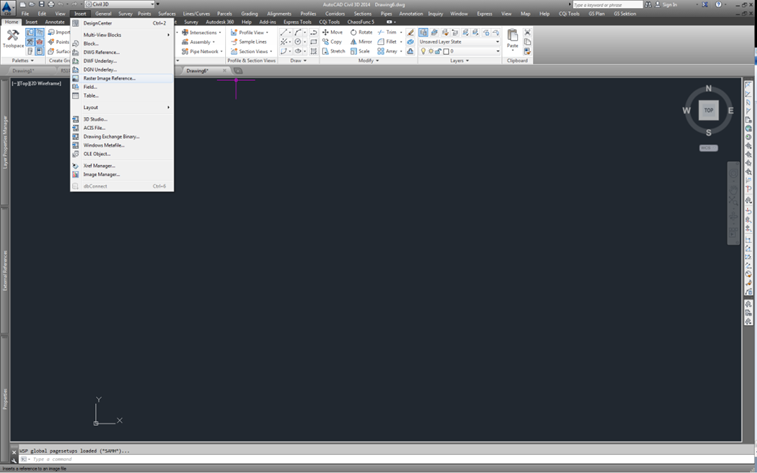
2) Choose Specify on screen for both Insertion point and Scale. Place the picture anywhere in CAD.
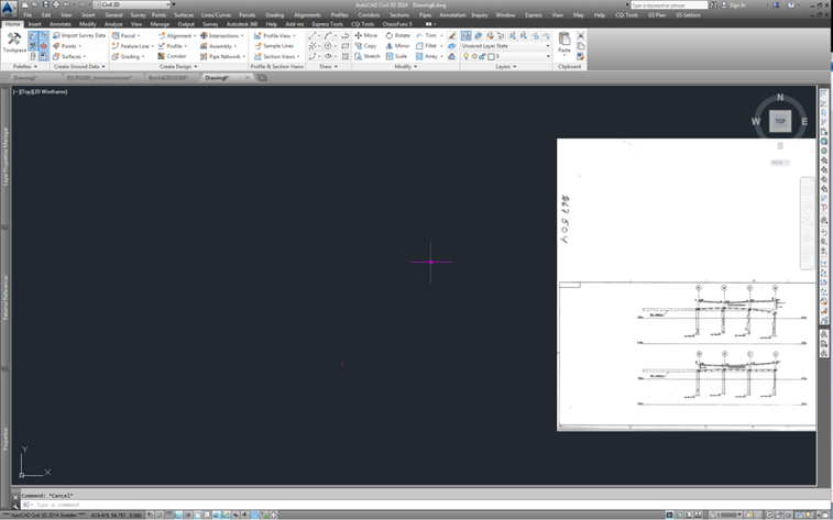
3) Decide what part on the drawing which should be fitted and measured.
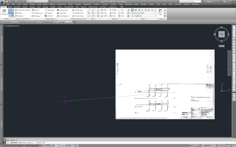
4) Draw a polyline with the same measure as the original drawing. In this example a vertical line of 5 meters was created.
5) Use Adersheet to fit the original drawing with the vertical line.
6) Drag reference lines [in this example a horizontal line at level +15]
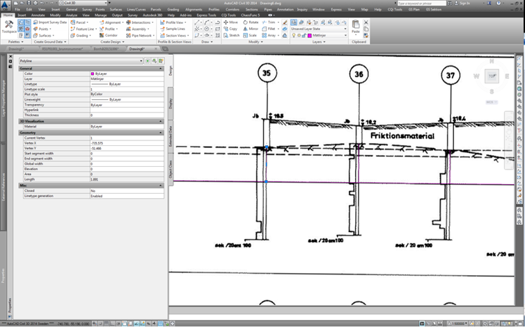
Sometimes a drawing can be skew, to determine how wrong the measurement is then control points in the original drawing can be measured. Measure both sides of the boreholes.
If the fault is negligible then draw vertical lines against the reference line from the points where measurements will be made.
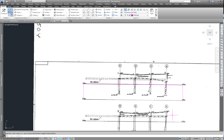
7) When giving the level for the boreholes mark one line at a time and check the length of the line in properties, in this example it is 1.891m. If you add 15 then the height level of the original drawing will be achieved, the correct height will be +16.891.
8) In Excel
Write down the boreholes and their ground levels. Change the levels accordingly to the height system for the project. Ex. From RH00 to RH2000 add 0.52m to Z-level.
In a surveying software
Open an empty .geo file and press F2 to open a list in the program and write down the boreholes and their ground levels.
When this is done then the levels can be transformed by using Data->Modifiera punkter and simply adding a constant to the levels.