Trimble Business Center

 View Only

 Slope/Slope Corridor Instruction - Using Tables

Katie Byron's profile image
Katie Byron posted 08-24-2021 13:06
Does anyone know what this "VC Length" is in Station Slope Table. I am trying to use the "slope/slope" corridor instruction to intersect the roadway cross-slope to the side slope of the road. However the side slope varies between 2:1 and 3:1 throughout. I thought I would use the tables, but there is obviously something missing that it isn't building the instruction out. It should look like the left side, the right side is the result of adding the slope table but it isn't adding the instruction.


Any help is appreciated!!
Katie

Ronny Schneider's profile image
Ronny Schneider
Hi Katie,
the chainage you are looking at is 0+000.000 and your station/slope table starts at 9+975. It doesn't take affect yet.

The VC length seems to be an offset from the alignment string. If you click into one of those fields you can enter the value by moving the mouse around in the template view. BUT, I have no idea what it does. I had a quick play with it in V5.52 and my surface (width) doesn't change whatever value I enter. I also couldn't find a reference to it in the F1-Help. The only one who probably knows what this one is good for is @Alan Sharp.


Alan Sharp's profile image
Alan Sharp
In the US where Super Elevations start and end instead of eg just going from -2% to a changing cross slope - (an angle break in a superelevation diagram) designers use a Vertical curve of eg 50' length in the cross slope table to smooth the transition in and out of superelevation over 50'. This effectively uses the slope change point as a VPI and places a 50' vertical curve into the slope table instruction

If you want to use the vertical curve you just add 50 into the vertical curve field. If you dont use them leave it at ?

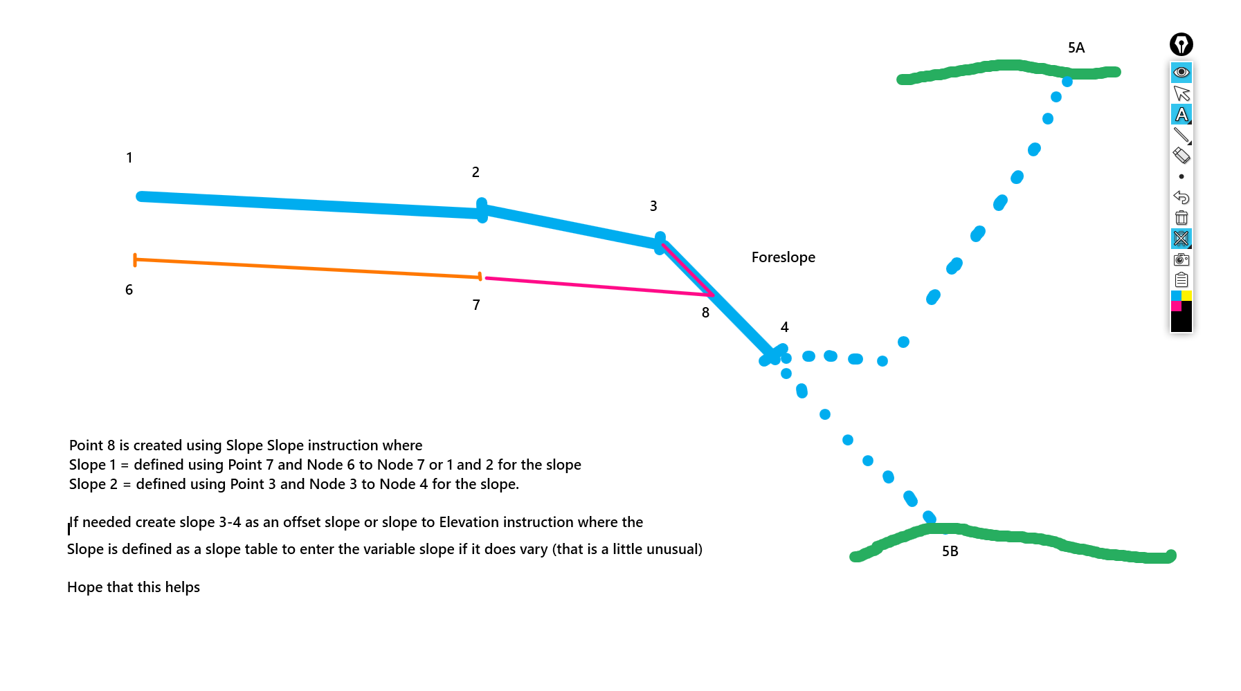
When I use this instruction, I normally use node to node to define the two slopes - for the first slope I use the end of subgrade eg point 5 andf then node to node and use the slope of the pavement (node 1 to node 2) that way if the pavement is super elevating it is captured by the node to node, then for the second slope I would use the Hinge point 3 and normally the slope from the Hinge to daylight or hinge to toe of foreslope (the foreslope is the first part of the sideslope that is always there in Cut or Fill to cover all the subgrades before the tie in Fill or the Ditch and tie in cut -0 by splitting the sideslope into two parts - Foreslope and Tie Slope you always have the Foreslope to tie out to and it is always there whether you are in cut or in fill.

If the Foreslope / Sideslope is varying in cross slope, I would normally create that as its own instruction first from Point 3 and then use the point 3 and the base of the foreslope eg 4 as the node to node

The issue that you may be having is likely caused by where you are placing the slope slope instruction in the list - the direction (toward or away from the centerline) is determined by the node immediately before the slope slope instruction, so if that is on the Left side of the road it can send the calcs the wrong way

The Vertical Curve is not the issue here and is not used in this process typically.

Katie Byron's profile image
Katie Byron
Makes sense. I haven't had the right job yet to play around with corridors that have super elevations. That will be a whole other learning curve I would imagine. Though I have played with the super elevation function in the alignment editor. TBC must have just needed a reboot. I opened the drawing up fresh while reading your responses and edited the side slopes to add the table exactly how I did yesterday and any it went no problem.

Ronny, in this particular case the 0+000:1 station is the same as the 9+975:2 station. I never did use the slide yesterday to look, but the whole surface never built out along the length of the alignment. I probably didn't need a reboot of TBC, maybe just closing a reopening the corridor template editor would have worked.

Appreciate the help!