Trimble Business Center

 View Only
Expand all | Collapse all

Original ground in corridor

  • 1.  Original ground in corridor

    Posted 10-29-2020 23:50

    Hej!

    I have a corridor that I assigned an original ground-surface. The surface has a hole in the middle because of water. It's the surface that is marked in the planview in the screenshot. But in the corridorview it interpolate across the hole. This will make the cut-volume show cut in the water-area. Is there a setting I'm missing?


    /Magnus


  • 2.  Re: Original ground in corridor

    Posted 11-01-2020 09:46

    I have just looked at this Magnus and I have seen the following


    1) The Existing Ground when you put a Hole in it and then use the Existing Ground as Existing in the Corridor, will show you the hole in the surface as shown here but the hole is ignored when you create the design surface and tie it to the Existing ground on Left and Right Sides - and the sectional area is displayed shaded completely as also shown below.


    When you do the Corridor Earthwork Volumes I would run them 2x Once for the total corridor and once for the Hole boundary so that you can compute the volume associated with the hole and remove it from the totals for the entire corridor. 


    Alternatively if you only want the areas to the left and right of the hole then you would need to limit your design to only start at the edge of the hole outwards to stop it computing a volume in the area of the hole. You could also patch in the area of the Existing Ground into the Design Model so that Existing = Design in the area of the Hole, rather than having the Design at Water Level and the Existing where it is below the Design. Use a Surface Instruction and limit it to the Left and Right side of the Hole to create an instruction in the Finished Grade model.


    I don't believe that you are missing anything regarding settings - the issue is that a hole in a surface is actually a set of Null Triangles - the triangles are still there they are just hidden. If you set the OG Surface Color to RGB 100, 101, 102 you will see the hidden triangles. While the Corridor Model when it slices the surface as a ref surface sees and honors the hole, then you tie out to the OG you will see (in my model at least), that it is possible to tie to the OG in the area of the hole - so the Corridor Model is still seeing the entire OG surface. When you Tie out the Left and Right Side it sees a closed area and fills it with Cut or FIll and does not blank the area where there is no OG.


    However when you run the Earthworks Report it appears that the Hole is taken into account in the volumes becauseI ran a test on this example and I saw the following for Cut and Fill


    When I remove the Hole and run the Earthworks Quantities I get the following for Cut and Fill


    Cut = 11914.2

    Fill = 554.9


    When I add the Hole and run the report on the Total area I get


    Cut = 7404.7

    Fill = 2260.1


    When I run the report on the Hole Area only (and this one I don't understand yet) because this is the area of the Hole and there is no Existing Ground in this area


    Cut = 2905.6

    Fill = 1156.2


    If I run Surface to Surface with no Hole I get


    Cut = 11907.8

    Fill = 557.2


    If I run Surface to Surface with the Hole I get


    Cut = 6876.6

    Fill = 375.0


    I will discuss with Development tomorrow - Good question for a Sunday Morning ....


    Alan


  • 3.  Re: Original ground in corridor

    Posted 11-01-2020 23:02

    Thanks for looking in to this, Alan!
    I think I got the total volume right with a surface to surface calculation. The remaining problem now is cut volume in the section-sheets which shows cut in the hole. I can see my original ground-surface as a green line and it looks alright but the cut volume is still calculated there.


  • 4.  Re: Original ground in corridor

    Posted 11-03-2020 10:54

    This is the same issue Magnus - I will run some cross section sheets to see whether the changes made this week are picked up correctly in the section output drawings.


  • 5.  Re: Original ground in corridor

    Posted 11-02-2020 01:30

    Here is another question about one thing we not have seen before. Why does Cut show in some XS but not in others? What we have seen is that if we turn Default subgrade on it will show a grey area in the plotted sheet but nothing if we turn it of. In the same time we can se the grey and red area in the template view as you can see in the screenshot. Anyone know why? 


  • 6.  Re: Original ground in corridor

    Posted 11-03-2020 10:59

    That looks like a settings issue in the Cross Sections Sheet setup. I would have to get the data to look at that - impossible to say what setting you need to change without the data.


    Alan


  • 7.  Re: Original ground in corridor

    Posted 11-04-2020 23:35

    I sent you the projekt by mail, Alan


  • 8.  Re: Original ground in corridor

    Posted 11-02-2020 14:40

    So the developers agreed that there was an issue and have made some changes to the corridor model for the next release to support this Hole issue in the Existing Ground. They have sent me a screen shot of a change they made earlier today that addresses this, and they have said that the Volumes now reflect the answers expected and achieved with a Surface to Surface volume calculation.


    The section now looks like this when you have a hole in the Existing


    When it comes to Surface Ties - the Corridor is still computing the tie when it happens to hit the existing in the Gap zone, but because it is in a gap it does not complete any areas and compute any closed out volume areas. The diagram below shows the results.


    Thanks for raising this one - it is a corner case that we had never considered.


    Alan


  • 9.  Re: Original ground in corridor

    Posted 11-02-2020 15:17

    Frederik

    The Default Subgrade appears when the software does not know what material to use. This can happen in two situations primarily


    1) No Subgrade Material has been defined therefore default subgrade is used

    2) there are two materials defined for the same area, creating ambiguity in the result - this happens most inadvertently by mistake, and it is often not clear where the problem lies. Take the example below as something we want to achieve


    Lets now say that point #3 is computed from Point #1 using a sideslope instruction so there is a line going from 1-3 in the template. and along the base of the cut we assign the Blue hatch material, we also assign that same material as being above the line from 1-3 because if we dont (in the current TBC release) the blue hatch would tie up vertically to the orange line and stop, leaving a triangular wedge in the two sides of undefined material (that is addressed in the next release also). 


    Then we create the orange subgrade line that ties with the line between 1 and 3 at point 2, and above that we define the purple dot material. That creates a vertical tie up from the ends of the Orange lines to where it hits the existing Grade (Green Line), again leaving a wedge at the ends - in this case on the left side the wedge will be the Blue Hatch Material that is defined along the line from 1 to 3. SO we think - OK lets add a connect instruction from 2 to 3 and above that we say use Purple Dot Material. Because the lines from 1-3 and 2-3 occupy the same exact space from 2-3 we now have a conflict of materials here (two are defined) and as a result we get a Default Subgrade in the wedge.


    This can also happen in situations like this


    We use a Template to define the Red Outline Design and maybe add a surface instruction to define the Pink overcut area. Note that the Pink line extends above the red line. If we say above the Overex surface is the Orange dot material and above the red lines is the purple dot material, the area above the red line will show as Default Subgrade because the little part of the pink line that extends into the area above the red line says use Orange Dot in here and the Red line says use purple dot in here - the clash triggers the Default Subgrade reporting. In this case, you can use the Clip Surface Instruction to Surface function in the surface instruction, and that will clip off the loose end of the Pink surface and fix the issue in this scenario


    A couple of other points here


    1. When you define the Material Layers, if you don't specifically need to call out / create different surfaces for all the Material Layers, you can just assign all them to "Subgrade" even if they represent different layers of material - this way the software works out how to assign the materials  and will flood them into all of the areas above the instruction to which it is applied including laterally into the wedge areas mentioned earlier in this post. The above examples of trenches are especially modeled better with this approach, as that eliminates the wedges at the edges (hey that is catchy - I am going to start using that more often!!)  
    2. You do not need to assign a material above every segment of a Material Layer - i.e. if you define a number of instructions for eg Subgrade Layer 3, and they are connected together at their end points, you need only assign the Material above on one of the instructions. This can help to mitigate the Default Subgrade from happening.
    3. As mentioned above, we have just made a change to the Material Layer Definitions that allow you to specify whether or not you want them to tie vertically from their ends or not. This is specifically for the scenarios above where the orange subgrade line would tie up to the Existing vertically leaving either undefined subgrade wedges at the edges or the wrong material wedges at the edges as shown below


    In the update if you disable the vertical ties at the ends of a material layer, it can flood also into the wedge areas giving correct quantities. Currently you would have to add the red line portions above the orange line to the material layer to get those to volume out correctly and avoid the double assignment of material issues mentioned earlier.


    I will record a video on this this week to demonstrate the problems and solutions.


    Note if you have the two materials issue, if you can offset the instruction vertically by a small amount e.g. 0.01 for a surface instruction, that can leave a small gap between material layers that eliminates the double material problem also, because each material layer is in a unique location so the lower layer has one material and the upper layer a different material and therefore no conflict.


    Hope that this partially answers the question at least.


    Alan


  • 10.  Re: Original ground in corridor

    Posted 11-02-2020 16:09

    We have also addressed this we hope in the upcoming release as I too have seen this a lot - part of the issue is that on Templates there are settings that get partially controlled by classification of the surfaces - so when you use a Surface Instruction for Design and another for subgrade both surfaces need to be either classified the same way or they both need to be set up also as reference Surfaces in the corridor - that way you can get at the controlling settings that are shown here (click lines by the TIN models on the reference surface in the Template Editor to access the Properties


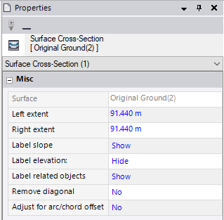
    The Adjust for Arc to Chord setting gets applied differently for Design Surfaces to other surfaces - this adjusts the positions of the nodes in the cross sections to account for the chording of the lines in the model caused by the TIN model, and adjusts them based on the curvature of the alignment at that station - on the outside of the curve this pushes the nodes away from the Centerline, and on the inside of the curve pulls the nodes closer to the centerline, if you look at a station where the design data was computed - most of the time everything looks good, however move to somewhere between the sections from the design data and you get the Default Subgrades - this can cause the issues that you are seeing - if one surface instruction is a Design Classification and another is not, then the default behavior for one surface is to have this setting set to Yes (the Design Surface) and the other to No (the Non Design Surface). When this happens, where two surfaces should tie, they actually miss or cannot find a vertical tie because one node is adjusted and the other is not - this will often affect you along the edges of a Design model as shown below


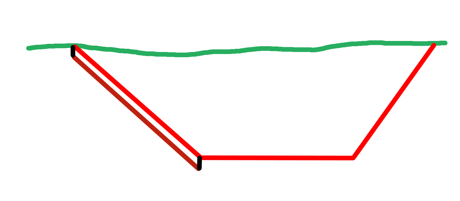
    The Red Line is the Finished Grade and is set to Design Classification and has the Adjust for Arc / chourd offset set to Yes


    The Brown Surface is a Topsoil Replacement layer (base of) and that is a surface instruction set to Unclassified and therefore has the Adjust for Arc / chord offset set to No.


    When Arc to chord is set to Yes this is what happens


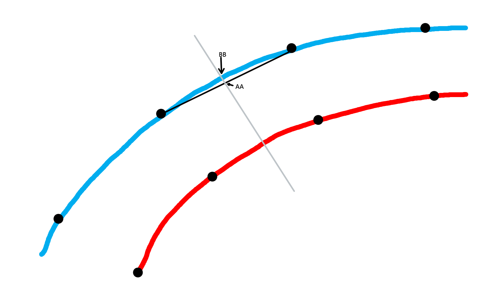
    The TIN Model along the grey station section line shows the point to be at AA (this is the unadjusted position), and if the Arc/Chord offset adjustment is set to Yes then the node AA is moved mathematically to position BB. On the inside of the curve the movement is toward the centerline. so if one surface moves the node, yet the other surface does not, then the two nodes are no longer in exactly the same place, which can leave a gap that can cause failure to tie up to the surface above (leaving no material fill in the template editor) or can leave a gap through which materials can flood and that can cause either the wrong material or Default Subgrade (because 2 or more materials are defined in the same area of the section.


    So set the surfaces for the Design and Subgrades to have the same settings here and also for the Remove Diagonal (which really only applies to Design Surfaces and Design Subgrades) to eliminate the warping effect that can happen between two source strings in a Surface Model where the elevations create two alternative surfaces as shown below


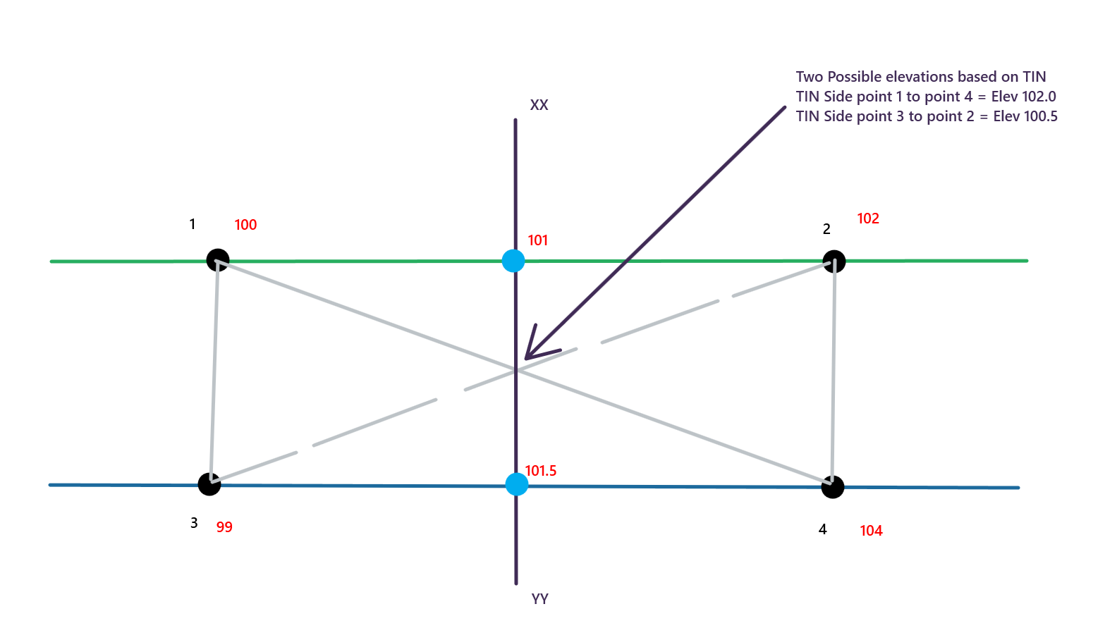
    The surface is created from2 strings (the Blue and the Green lines). At the location indicated by the Grey Section line we are slicing the surface model TIN. At this location we would have the point at which the section crosses the two strings (the Blue Dots) and also a point where the section crosses the TIN side between either points 1 and 4 or 3 and 2. The slope between the two strings gives an elevation at the mid point of 101.25, however the two TIN options give elevations of 102 or 100.5 (both of which are incorrect in this scenario (this is one of the known issues using TIN models). So in a corridor model we know things are computed perpendicular to the centerline, and we know that the strings typically indicate the start and end of a linear slope - so we can basically ignore the "diagonal" and just use the strings to define the surface instruction, thereby eliminating the errors caused by the TIN side interpolation. This can improve the section as shown below


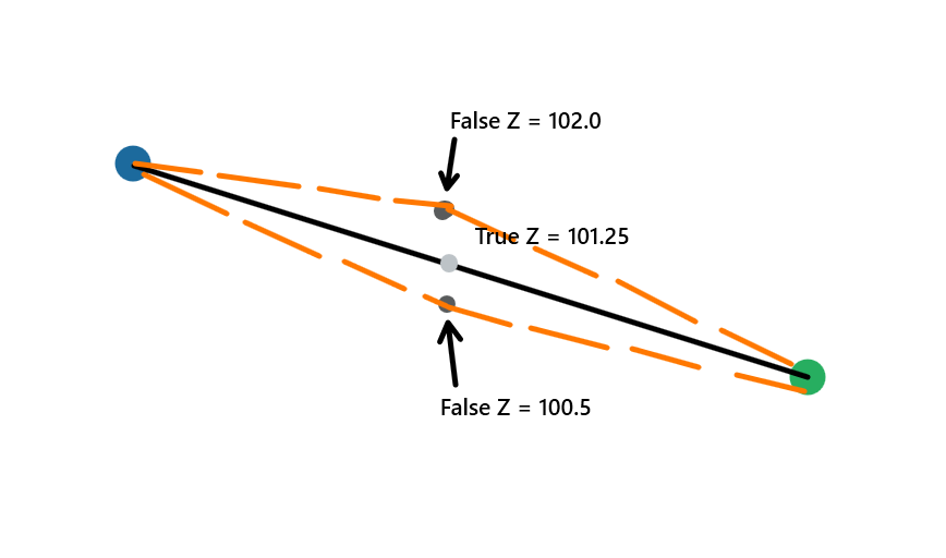
    If you did not apply the remove diagonal then you would get one of the two orange surfaces at the indicated location between the two strings. If you apply the remove diagonal then you will get the black line between the two strings and the right answer for the surface. This really only applies to Design Surface models that have been constructed from 3D strings interpreted from a corridor like model (similar to that of TBC e.g. Civil 3D, OpenRoads Designer, 12D etc.)


    When you see the Default Subgrade or No Material defined, then this should trigger the research into the above issues and trying to solve by fixing the problem in the data / model.


    Hopefully this helps to explain the issues you are seeing - you have to put them into your own context, but these are the most common issues and causes.


    Alan


  • 11.  Re: Original ground in corridor

    Posted 11-02-2020 23:30

    Hi!

    Maybe I just don't understand your explanation, because of my lack of higher education credits, but why does not the cut and fill show the same way in the sheet set as in the template editor? In the template editor everything looks alright and I get cut and fill as expected (except for the hole but this we already handled), but in the sheets the cut and fill doesn't follow my bottom(the red line). Now I also added a defined subgrade on the right side but I see no difference.


    Template editor


    Sheet