Trimble Business Center

 View Only
Expand all | Collapse all

Create Site Improvements with Slopes/Edge Properties

  • 1.  Create Site Improvements with Slopes/Edge Properties

    Posted 01-22-2019 16:50

    Most of the projects I build models for require excavation and backfill that requires a slope. Instead of building my site improvements as offset sections based on layer width and average depth, is it possible to have an edge property for the site improvement similar to the topsoil replacement site improvements? I either have to have a footprint that is a proportion of the actual width, or material depths that are a proportion of the actual depth to account for the slope that daylights out of the excavation. I have attempted to utilize the corridor feature but that seems unnecessarily time-consuming for typical sections of areas such as pads and foundations. 


  • 2.  Re: Create Site Improvements with Slopes/Edge Properties

    Posted 01-23-2019 14:09

    I think I understand your question, could you draw me a couple of diagrams (Rough drawings are OK), to show me in Plan and Section what you are requesting. I will see if I can recommend something to you to try and will put in the request to development for what you need (depending on what I find here).


    Thanks


    Alan


  • 3.  Re: Create Site Improvements with Slopes/Edge Properties

    Posted 01-23-2019 15:20

    Here is a section of something that I might see. With the frost susceptibility of the soils and structures in Alaska, many foundations and have deep excavation and sloping, along with insulation. These sections are found on activities that require excavation over large areas, not linearly, which would make sense to use a corridor. How would I model something similar to this incorporating site-improvements with materials and slopes? I could find a perimeter for my bottom of excavation and use that as a contour, but then I am not able to build me site improvements upwards from bottom of ex, instead of down from finished grade. At least that I am aware of.


    I hope that makes sense. The solution I see would be to allow site improvements to have slope properties so the perimeter is defined by the site improvement boundary and then the slope is an input. The site improvement would then daylight at the design surface dependent on the slope and depth of the total improvement. 


  • 4.  Re: Create Site Improvements with Slopes/Edge Properties

    Posted 01-23-2019 16:31

    You could use the Create Sideslope option from the base of excavation and put in the first node at the Offset / Slope or Elevation Delta and Slope to the Top of Sand Bed, then you can do a Vertical Offset to get to the Top of the Insulation Board, and then a third to compute back to the side slope line and then a side slope to the Existing Grade. This will work on a line or polygon feature. It will give you the lines that you can use to create the different surfaces from which you can compute your volumes. Note however you may need to add those lines into Takeoff Surfaces if you want to use the Takeoff Calcs to run your Quantities (Use Add and Remove Surface Members to add the lines from the Sideslope to the Takeoff Surfaces that you have created. 


    I will try to mock this up in a sample project for you to test my thinking here - but it should be possible to get the "surface Models you need using Sideslope command to at least create the linework that you need to create the models. You may need to run sideslope twice or so to get exactly what you need - I am not sure how complex a sideslope we can create in one pass - but this is a good test for me to look at


    Alan


  • 5.  Re: Create Site Improvements with Slopes/Edge Properties

    Posted 01-23-2019 18:08
      |   view attached


    I used the Create Sideslope Command to create all of the 3D linestrings needed for all of the Surface Models - when you use this command, ignore the material Layers and just place all of the Nodes you create on the same material Layer. This will create you all of the 3D Lines. Make sure that you name them clearly like Top Of Sand etc. So that it is easy to select the lines afterwards to create your surface models. Once all the Strings are created - u=you can create the surfaces that you need pretty quickly. 


    In order to compute Surface Volumes - using all of these surfaces, you may have to create a Corridor (Straight Line Alignment), and then a series of Surface Instructions using the surfaces you just created and then assign Materials Above each surface. You can then run your corridor quantities. You cannot unfortunately create Takeoff Surfaces for these Interfaces in any easy way at least - but the Corridor approach lets you compute the volumes quickly and easily provided you created your surfaces in a "smart Way" so that Material Assignments are easy to do above each surface.


    Failing that you can compute volumes between pairs of surfaces to get the volumes you need from the model.


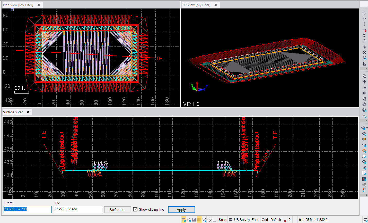
    I used a simple rectangle in this example, just to see if this was possible using Create Sideslope command


    Note when you draw your corridor alignment, you really don't want it to be square on to the walls of the inside wall, because when you create volumes using say a 5' increment, you could miss the wall entirely on both sides (cross section areas), or you could hit it at one station and not the next so you will get a lot more concrete than there should be, if you bring your alignment across diagonally, then it will pick up the wall volumes way more accurately, you can also only use 1' or higher intervals for computing a corridor, so a 0.5' wall could be missed entirely even at that interval value (but it will get you closer - in this case the wall volume is ~167 yd3 of concrete, yet if I have the alignment square on and compute at 5' intervals I get 242 yd3 and if i do at 1' intervals I get 174.6 yd3. If I change the alignment to be diagonal, even at 5' intervals I get 167 yd3.


    You will also need to create a surface that follows the top[ of all elements (I called mine Top of materials), and then used that as an additional layer in the Corridor so I could create the correct Backfill Material, and I also had to include the inside of the Wall and the Inside of the containment area as part of my Finished Grade Model to stop it getting filled - you can see that in this version of the project.


    This was a great test and a really good teaching example (I do a lot of training so I will use this example in my next set of classes) to show how to do this.


    Here is a short video


    Thanks


    Alan

    Attachment(s)


  • 6.  Re: Create Site Improvements with Slopes/Edge Properties

    Posted 01-24-2019 11:04

    This makes sense. I don't have the practice with corridors that I should so please give me some time to try to replicate this process. I have been trying to utilize the categorized layers and site improvement features to define my volumes. It seemed to allow for a more streamlined process than creating corridors. 


    I will let you know my results when I have a moment to test this out. 


    Thank you very much for the time and effort to follow through on this.