Trimble Business Center

 View Only
Expand all | Collapse all

Creating a Side Slope

  • 1.  Creating a Side Slope

    Posted 11-13-2020 05:38

    I am trying to create a side slope that has a slope of 2:1 for most of it but then where it transitions back to the existing ground it is more of an arc. As you can see by what I have attached below. Is there a way to create an arc using the corridor templates commands.


  • 2.  Re: Creating a Side Slope

    Posted 11-14-2020 20:23

    Nathan

    You couple create a "Pseudo" arc using a series of chords using the Sideslope and select the Slope by Depth Table to define the series of chords that define an approximate arc of the radius you have in the design - I would draw it at 1:1 in the plan view and then compute a series of arc chord elements that follow the shape - the slope by depth table allows you to define any number of segments, and whichever one ties to the existing will terminate the sequence. While not straight forward it looks to me like it should be possible to do it that way.


    Do you have the design radius for the arc?


    I could take a look at this for you on Monday if you have the design standards for that element


    Alan


  • 3.  Re: Creating a Side Slope

    Posted 11-14-2020 20:25

    Is this a model for Machine Control or a Model for a Bid / Takeoff. You have the cross sections for the job, you could flip those into 3D and then use them to build the model also if for a Takeoff / bid.


    Can you share the sections?


    Alan


  • 4.  Re: Creating a Side Slope

    Posted 11-16-2020 05:02

    Alan,  

       This is for a 3D model to use out in the field for Machine Control and handled rover set up. I have attached my TBC project and also the PDF plans to the post above.


  • 5.  Re: Creating a Side Slope

    Posted 11-16-2020 15:40

    Nathan

    From the provided Sections you can convert them to 3D linework using the Create Stored Sections from CAD command. This process will need you to use the Divide Line command on the curved embankment elements to chord them into e.g. 2' sections, and will at least give you the Daylight Line and start of curve, end of sideslope lines to work with. 


    Because the design does not give you the design criteria to build the arc elements from, this is the best that you have to go on. The file I sent you which has the flipped sections and Finished Grade Model may help you somehow I hope.


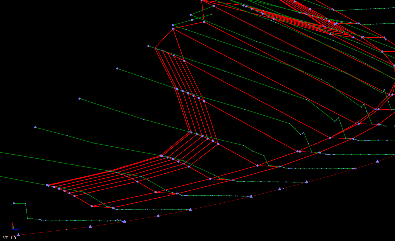
    This is where I got to. I thought that maybe you could use the Sideslope with the slope by Depth Table function to create the pseudo curves, but because they are not a fixed radius I don't think that is possible. 


    So without the contours of the sideslopes to work with and just this limited section data, this is the best I can do with the tools available today.


    If they could give you sections every 20 feet or 10 feet then we could do more if that is all the engineers can generate


    Alan


  • 6.  Re: Creating a Side Slope

    Posted 11-19-2020 16:34

    I cant help but think that what I am seeing in your cross sections is just slope rounding. I believe this ends up being a flat 4:1. yours appears to be about 8 ft in width with about two feet of vert between d/l og and d/l cut slope. It creates a small hinge in the surface but is easily blended in the machine: I would run my side slope up to catch as a non material(NM), o/s a node at 4ft in of the catch(NM), slope/slope to the surface node(NM), connect toe to new hinge as finish mat, side slope as 4:1 to catch. 


    This is my simple handling of slope rounding. If adjust for overcut in the machine is turned off, whatever hinge is left in the finish slope can be straddled and blended between the slope faces. 


  • 7.  Re: Creating a Side Slope

    Posted 11-19-2020 17:22

    I figured I should give an example more representative of your cross sections.