Trimble Business Center

 View Only
Expand all | Collapse all

Has anyone else run into issues with profile plan sets not printing Cul-De-Sacs?

  • 1.  Has anyone else run into issues with profile plan sets not printing Cul-De-Sacs?

    Posted 02-08-2019 07:17

    I am having issues getting my profile plan set to show my Cul-De-Sac. The plan view appears to stop at the ending station of the alignment but because it is a Cul-De-Sac, the whole Cul-De-Sac is left out. Is there a way to avoid this? I tried both a rectangular dynaview and a fit dynaview but neither seemed to fit this in. This alignment is particularly tricky because it comes back on itself parallel not perpendicular like traditional Cul-De-Sacs.


    View of my Plan set


    What I am trying to get the plan view to look like or encompass


    Thank You


  • 2.  Re: Has anyone else run into issues with profile plan sets not printing Cul-De-Sacs?

    Posted 02-08-2019 16:19

    Is the Cul De Sac a Cul De Sac Object or just part of the design surface?


    Alan


  • 3.  Re: Has anyone else run into issues with profile plan sets not printing Cul-De-Sacs?

    Posted 02-08-2019 16:22

    Part of the design surface. It is one of those wonderful ones that wraps back in on itself.


    Patrick L'Heureux, E.I.T.

    Severino Trucking

    (603) 340-2578


    Sent from my iPhone


  • 4.  Re: Has anyone else run into issues with profile plan sets not printing Cul-De-Sacs?

    Posted 02-09-2019 05:17
      |   view attached

    Attached is the file.


    Attachment(s)

    zip
    TBC Community.vce.zip   14.28 MB 1 version


  • 5.  Re: Has anyone else run into issues with profile plan sets not printing Cul-De-Sacs?

    Posted 02-13-2019 14:38

    So looking at the HAL I see what you mean about it looping back on itself, 


    The solution to your problem is however relatively simple.


    When you build a Plan Profile Sheet, the Plan View is created using a Drawing Frame that is created in the Plan View, That by default is terminated at the end coordinate at the alignment and perpendicular to the tangent of the alignment at that location. However the frame is created and can be edited like any Dynaview Frame. So I just highlighted the Dynaview frame in the plan view and then used CAD Grips to drag the end of the frame beyond the cul de sac to where I thought you needed it and that updates the sheets automatically to give an extended Plan View that meets your needs.


    You can within reason move (at least Left and Right of CL) and change the shape of the Dynaview (within the scope of the size of the Plan View Window on the Plan / Profile View.


    If that answers the question - then I am glad that we can meet your needs. If this doesn't do what you need then let me know and we can dig in further.

    Hope this helps


    Alan


  • 6.  Re: Has anyone else run into issues with profile plan sets not printing Cul-De-Sacs?

    Posted 02-14-2019 06:21

    Alan,


    Short Term -Solved

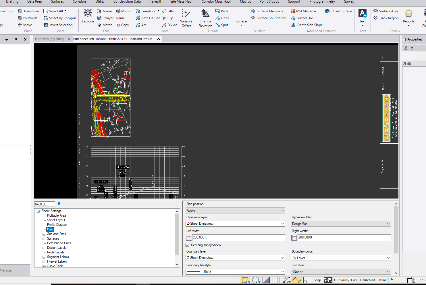
    This works great. Thank you pointing this out. That does help to quickly manually manipulate the dynaview and fit what you need if the automated view does not grab it.


    Long term - #enhancementrequest

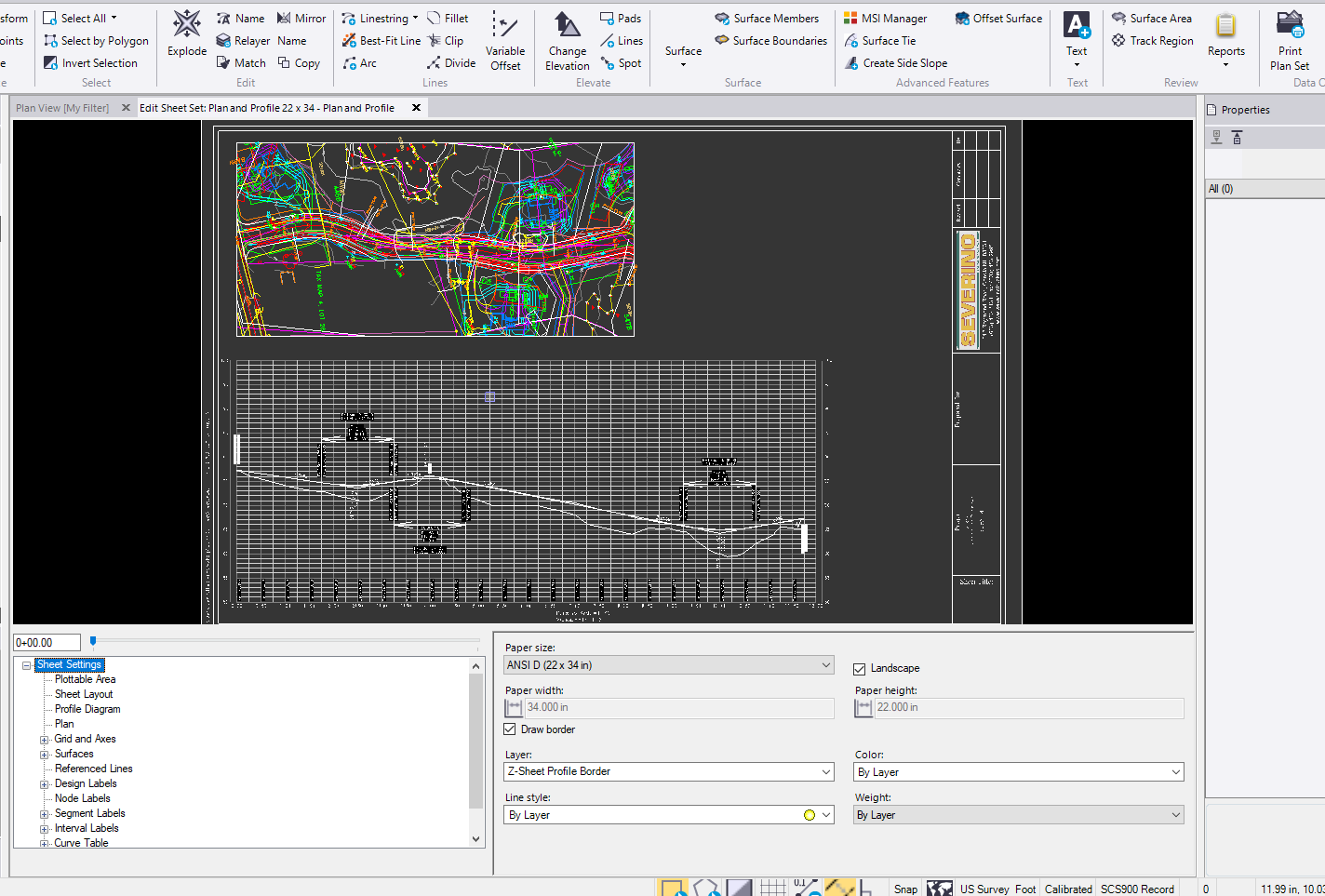
    I am hesitant to say it solves the issue because we do a lot of these subdivisions (shown below) and every time I make an edit in profile settings and rebuild sheets I need to remember to go back and tweak the plan view dynaview. This definitely adds another step to forget when you are throwing together deliverables. When I choose to build sheets, I want to get that sheet as close to perfect as possible so I don't have to worry about missing something if I am in a time crunch.


    In an effort to automate the process more I would to put in an #enhancementrequest for starting and ending station offsets in the Plan settings.


    Suggestions:

    • Have the profile run a check on the alignment to see if:
      • The ending station is within a range window ( something like +/-.5 horizontal) of the rest of the alignment
      • If it is, run a distance check between the 0+00 and the ending station and the further station from 0+00
      • Use the furthest linear distance from 0+00 as the plan end
    • Allow for offset inputs form the starting station and ending station
      • At the start:This would allows you to apply a negative offset to see more of the plan view at the start of an alignment
      • At the end: this would allow you to see more of the plan view 
        • Or a linear distance from 0+00


    There will always be need for manual manipulation (you cannot automate everything...yet) but if we can apply offsets and have the profile plan view spit out the same results consistently it makes things a lot easier when there are revisions or updates to entities. That saves me and other users from going through all of the workarounds we had to perform to get to the final product and make sure you updated them as well. Something I feel is part of the issue with engineering plans I see today. A lot (not all but a lot) seem to use methods that are do not dynamically update with changes, so if they change a cross sections it does not regen everything else and you run into issues with plans sheets, profile, cross sections and typicals all potentially differing. What is right? Those are the worst.


    Which brings me to another thought, could we flag cross sections sheets and profile sheets that need to be updated because of changes to a surface? #enhancementrequest


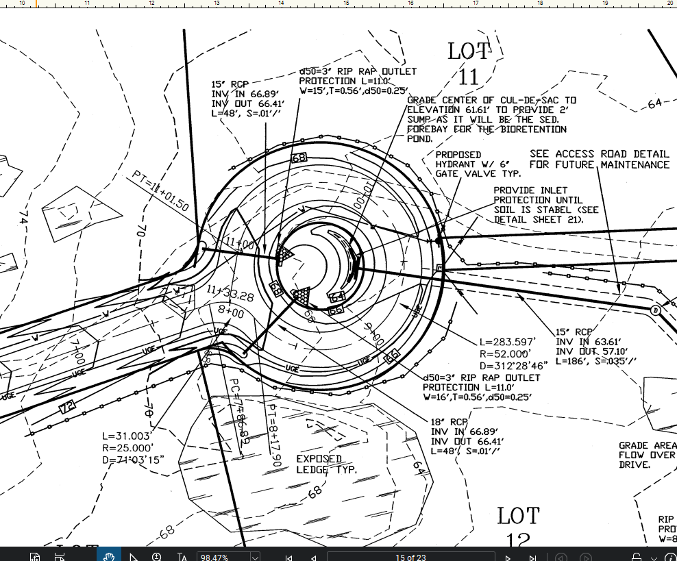
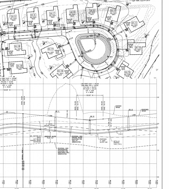
    Cul-De-Sac Examples:


    This project consisted of two Cul-De-Sacs both similar shape


    This project had 2 that were tear drop shaped but same issues
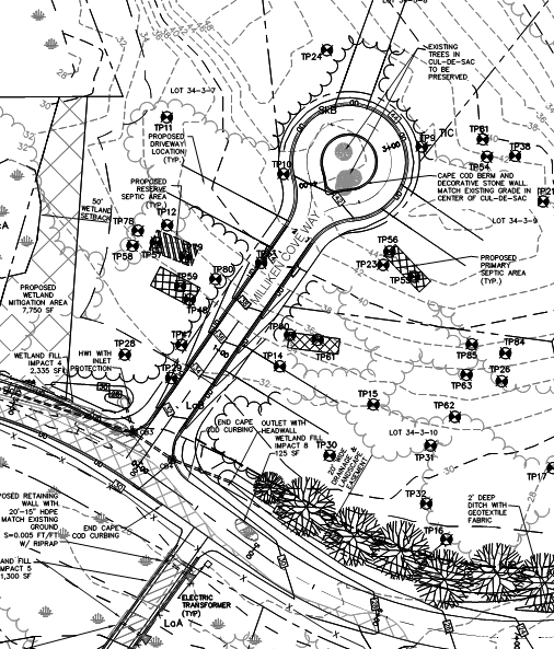


    Another example


    Thank You!


  • 7.  Re: Has anyone else run into issues with profile plan sets not printing Cul-De-Sacs?

    Posted 02-26-2019 16:53

    Can you send me the original PDF Pat?


    The Alignment Profile Issue - I confirm that that is an issue with these type of wrap back alignments in terms of the way we draw Plan / Profile (Profile specifically)  - developers have looked at this - it is not a trivial solution to solve -will let you know if they resolve it. It is caused by what we call Alignment Extensions - if you follow the alignment with an active cursor like Explore Object - you will see that the alignment is extended  and it is the way that those extensions are being handled by the profile alignment tool beyond the end of the alignment that is causing the issues that you saw. I will be in office tomorrow and will find out what the plan is here to resolve


    Alan


  • 8.  Re: Has anyone else run into issues with profile plan sets not printing Cul-De-Sacs?

    Posted 02-27-2019 03:27

    Alan,


    I sent that file to your email.


    I have noticed the line extension issue. This can cause some trouble when using templates instructions because sometimes the station will be picked up by the projected alignment and not the portion of the alignment you are closest too.


     I have had headaches with SCS900/Siteworks because of a similar issue with linestrings. This is something I have made aware to the team but a very similar issue occurs when you are trying to stake this centerline. The station is produced from the projected alignment instead of pulling information from the nearest station along the alignment. I get this results when staking a linestring as centerline and drapping that over the surface. I tested .pro and they handle this better. I would asssume .vcl will as will.