Brent
You can do this as follows - however be aware that this is not a precise solution because a 3D TIN model is a complex beast to offset all faces perpendicular to the faces because each TIN Node is in at least 2 or more triangles, and you would have to compute the Perpendicular points to not just all of the face nodes but also create additional nodes around each node to accurately model the perpendicular surface (this would bloat a surface enormously and is extremely difficult to do this in 3D and achieve any form of accurate surface. However this is what I would do.
1) I would densify the source surface first (typically by creating a surface elevation grid at e.g. 10' intervals across the surface and then use Explode to convert it to Points and then add the created points to the original surface to increase the density of points in the model (use Add / remove Surface Members).
2) Create a Surface Edge Breakline around the Surface or a boundary around the area(s) of the surface that you are interested in. If you create boundaries, you should then use the Change Elevation command and set the elevation of the Boundary Line to that of the Surface with no vertical delta. This effectively drapes the boundary line on the surface.
3) Check the Properties of the Boundary / Edge Breakline and set the Surface Sharpness property to Sharp and Texture Boundary
4) Add the Edge Breakline and or the Boundary Lines to the target surface (which you are going to offset)
5) Create a Material in the MSI Manager under the Earthen Section with a name that you can easily find e.g. Clay Lining or Toposoil Strip
6) Create a Site Improvement in the MSI Manager called Topsoil Strip, in there you can set by Perpendicular Offset and you can define one layer of material at the thickness you want using the Material you created in (5) above.
7) From the Surface Menu use the Apply Surface Site Improvement command (Site Improvement) - select your target / reference surface, Give the Site Improvement a Name like Clay Lining Base or Topsoil Strip Base, place the Site Improvement "Point" on a layer called SITE - Site Improvement Markers (or similar), select the Site Improvement that you created in (6) above and then place one dot in each of the boundary areas. Note that because the lines have the Texture Boundary Property they will limit where the site improvement is applied.
8) Now you can use the Create Subgrade Surface command from the Surface Menu to create the adjusted surface - give it the same name as you used for the Site Improvement Name in (6) above e.g. Base of Clay Lining select the reference surface and then select the Site Improvement for which you want to create the Bottom Surface from the list in the Create Surface at part of the dialog. Select the Bottom of surface if you want its base (which you do)
This will generate a Subgrade Surface that you can review in Surface Slicer or add to a Corridor Model. In the Slicer or Template or Cross Section Editors you need no vertical exaggeration (so it is not distorted, and you should see that the surface is pretty uniform thickness. Where there are sharp grade breaks in the reference surface, you will find that from the break either side to the next point in the model the thickness may vary slightly, however for quantity purposes you will find that this is more accurate than using the Vertical method (for applications like Clay Linings in Landfill Cells etc.
We do place a Caveat on this that it should be used for Quantities only and not for stakeout purposes - staking the Finished Grade and then allowing machine operators to correct for Perp is better than using the subgrade surface here (unless you feel that is accurate enough for your purposes - it will be good on planar or rolling terrain, however around sharp breaks it will be less accurate around the breaks for the reasons outlines at the start of this response. For steps (near vertical jumps in the surface or very steep surface elements) it will likely be more incorrect) than on shallow or intermediate slopes. For slopes of any length and up to 45 degrees it will generally give pretty good results.
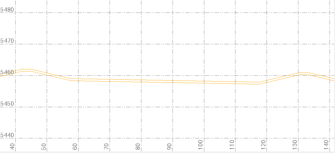

Here is an example where I modeled it without densification across an area of moderate slopes with Perp Offset of 8"
Below is the same area with a Vertical Offset of 8" (the difference is subtle but when seen during the process and when measured is more accurate above than below if you want an 8" Perpendicular offset.

Alan