Trimble Business Center

 View Only
Expand all | Collapse all

Drafting a Offset Profile

  • 1.  Drafting a Offset Profile

    Posted 03-12-2019 07:46

    When drafting a profile TBC grabs the elevation data from the horizontal location of the alignment in the corridor.  Is there a way to offset the alignment?  Lets say you are given multiple alignments that are all referenced to one BL and

    the BL is not located over any of the corridor data templates given there instructions came as surfaces.  Suggestions?


  • 2.  Re: Drafting a Offset Profile

    Posted 03-12-2019 10:41

    Is BL Breakline?


    not sure that I understand the question


    if you reference a Breakline to the Corridor it becomes "a surface" that you can plot in the profiles using Profile or Plan and Profile Plotting. The elevation is extracted from the Breakline surface elevation (it is treated as a surface that follows the Breakline - it uses the Station from the HAL and projects the Breakline onto the HAL.


    the Breakline does not need to be over a surface or over a corridor template in order for it to be plotted


    i am not sure why offsetting the alignment helps in this question - I don't think I fully get the question though - can you give more detail and I will look at it when I am back at work tomorrow


    alan


  • 3.  Re: Drafting a Offset Profile

    Posted 03-12-2019 10:43

    Baseline


  • 4.  Re: Drafting a Offset Profile

    Posted 03-12-2019 11:37

    What does Baseline really mean - is that a wall Baseline or something else


    Sent from my iPhone


  • 5.  Re: Drafting a Offset Profile

    Posted 03-12-2019 11:54

    It’s common for engineers in this area to have a Baseline alignment for a project used as the governing alignment that is used as a reference to establish other geometries.  You see this in levee building due to the change of the CL alignment due to shifting of the levee horizontally with each cap, or lift in elevation associated with levee enlargement that occurs over a period of time due to stability reasons.  Some plans for road design will have several alignments associated as CL roadway, CL ditch, and so on referenced to a Baseline alignment that doesn’t change.


  • 6.  Re: Drafting a Offset Profile

    Posted 03-12-2019 12:19

    Thanks Henry - so a Master Alignment - I will re read Pats post to see if I understand it any better now


    Alan


    Sent from my iPhone


  • 7.  Re: Drafting a Offset Profile

    Posted 03-12-2019 12:24

    Can you share an example


    alan


  • 8.  Re: Drafting a Offset Profile

    Posted 03-14-2019 12:36
      |   view attached

    Henry

    Thanks for the time today to discuss this on the phone. For the benefit of others I am going to restate your question as I understand it now and then provide you with the process of how to create your profile Plot


    The definition of a Levee is often going to be like that of a divided highway (so this response applies to both), in that the Main Alignment or Baseline that provides Stationing for the project is offset from the actual model surface of the levee itself. In the example provided I have defined a Master Alignment and then from that I have created a Corridor Model as follows


    I created the first Node - which is the Levee Centerline which follows the inside bottom of levee for example. You stated that the offsets along the main alignment can vary, so I created this node of the Corridor using an Offset Table through which I entered variable offsets for the Levee from the main alignment at different stations. You stated that the Vertical Profile of the Levee alignment will typically be the same as the Main Alignment profile - I would normally enter the Vertical Offset as 0 to achieve that, but because that would place the Vertical Profile of the Base of the levee at the same elevation as the Main Alignment profile I entered it as -2' so that we can see it in the profile drawing. For this node I did not include it in the Finished Grade Surface.


    From the Levee Centerline node I created a Top Of Levee Right at 10' Offset at 3:1 Slope

    From the Levee Centerline node I created a Bottom Of Levee Outside Edge at 20' offset and 0% Cross Slope

    From the Bottom of Levee Outside Edge I created the Left Top of Levee Node at -10' offset and 3:1 slope.


    The above three instructions are all part of the Corridor Finished Grade Surface model


    I then imported my Plan Set Template


    Before I can create a profile, that shows the surface elevations of the Top and Base of Levee for example, because the surface is offset from the main alignment, it is not "sliced" by the main alignment, so it cannot be displayed in a Profile Plot as a "Surface". So I first exploded the Corridor Model to create the Linework of the Model (4 lines). I then Edit those lines to convert them from Polylines to Linestrings (I have put in a request for us to also support 3D polylines in Profile Drawing methods). I then add the Linestrings that I want to draw in the profile (the Levee Center Line and e.g. the Top Right Line of the Levee for example) to the Corridor Model as reference Lines. Any Reference Line added to a Corridor Model can be drawn in the Profile Plotting - if you don't have a linestring (Surveyed or Created from a Model) then you can draw a line and drape it on the surface model using Change Elevation or Drape Commands to create a 3D Linestring to give you the profile that you want.


    When you have done the above, find the Profile Drawing Sheet Set of your Plan Set and select Edit from the Right Click Menu. This will open the Editor for the Profile Drawing. You will find all of your Referenced Lines in the List under Referenced Lines - you can select each one and set the Color, Layer, Lineweght and Linestyle for each of the Referenced Lines. You will see in the profile the Main VAL as well as the referenced Lines that you wanted to show. Al are computed / projected onto the main alignment.


    (Note: There is a defect in here that I have reported where the lists of Reference Lines does not update automatically - you may see the line appear in the Referenced Lines section but not as an individually listed line - if that is the case, close the Editor and Reopen It and you will see that it is refreshed - I have requested a fix to this also).


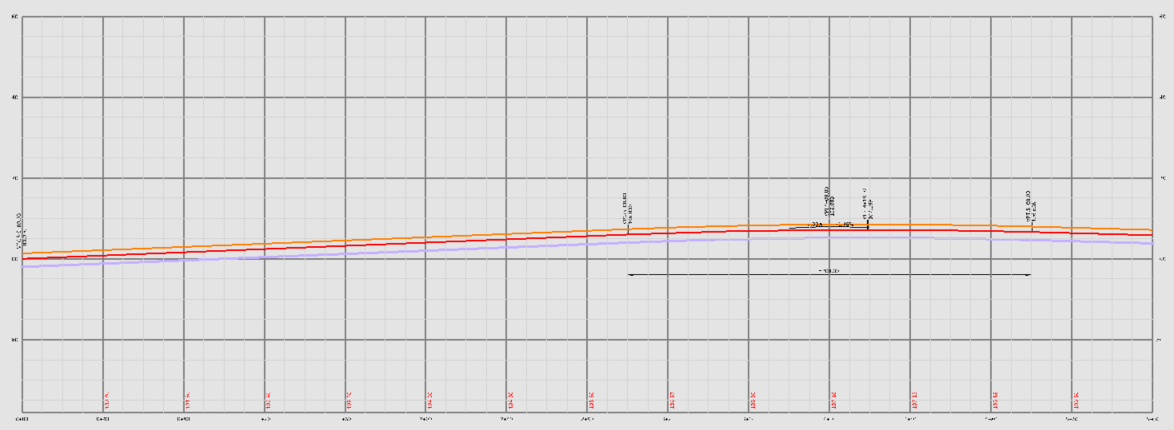
    The Red Line in the above image is the main VAL, the Purple Line is the Levee Centerline and the Orange Line is the Top Right Edge of the Levee.


    The Project File is enclosed if you want to review how this was done.


    Hope that this answers the question


    Alan

    Attachment(s)


  • 9.  Re: Drafting a Offset Profile

    Posted 03-14-2019 15:32

    Alan, having trouble labeling the profile.  Tried profile table – Rows, added label names – When you got to assign the text from the drop down menu it doesn’t work.  It also gives differing drop down menu’s when trying to select the properties of the desired txt.


    Attachment(s)

    zip
    WBV 15A.2 FINALS.vce.zip   4.84 MB 1 version


  • 10.  Re: Drafting a Offset Profile

    Posted 03-14-2019 16:45

    What are you labeling on the Profile -Elevations, Slopes or ???? Let me know


    Alan


    On Thu, Mar 14, 2019 at 4:32 PM hadams@phylway.com <trimble@jiveon.com>


  • 11.  Re: Drafting a Offset Profile

    Posted 03-14-2019 16:46

    Elevations


  • 12.  Re: Drafting a Offset Profile

    Posted 03-14-2019 17:10

    Use Interval labels and place at bottom,top or on profile


    Existing and Design are enabled at bottom - you can use those to see how they are implemented


    Alan


    Sent from my iPhone


  • 13.  Re: Drafting a Offset Profile

    Posted 03-15-2019 08:19

    Here is how I would Label Elevations Henry


  • 14.  Re: Drafting a Offset Profile

    Posted 03-18-2019 08:32

    Thanks Alan, it’s working fine.


  • 15.  Re: Drafting a Offset Profile

    Posted 03-18-2019 12:18

    Great to hear


    Alan


    On Mon, Mar 18, 2019 at 9:33 AM hadams@phylway.com <trimble@jiveon.com>


  • 16.  Re: Drafting a Offset Profile

    Posted 03-21-2019 13:59

    I've just spent a week working on same problem with more difficult solutions Thanks Alan again for a solution, but...

    Could we just get the ability to select any Node in the Corridor to generate multiple Profile lines/table entries, without having to generate "Reference Lines" externally and importing?


    Also my problem was a little more complex in that I needed to have a "Cross Section" also on the plot (Same page). I just needed a single page Long Section and Cross Section with the Plan overview. I ended up just have to screen snap a Cross Section View and importing as Image. Worked well enough for my case. But when changes happen it's redo it all and no Auto updated drawing.


    I know I could just draft a Page on Long Section and a 2nd Page with a Cross Section, but Its just a simple Typical Section I needed it just made PDF's cleaner to have all on one page.


    Thanks again for all the support.


  • 17.  Re: Drafting a Offset Profile

    Posted 03-21-2019 15:25

    If you have the Cross Section generated - you can draw a Box around it in

    the Sheet View and then create a Dynaview from it on the Same Sheet as your

    Profile. If you are creating a Profile - you can create it from the

    Corridor using the Create Profile or Plan / Profile  Sheet approach or you

    can create a Box around the profile View of the Alignment and then create a

    Dynaview from that as an alternative approach. You can add the Profile and

    Cross Section Dynaview to a Plan Sheet if the Plan is not filling the

    available space - so when you create your Plan - if the available space is

    say 8" Wide by 7" tall, then you can use a 4x4 for your Plan and then the

    remainder of the sheet is available for your Cross Section and Profile.


    If you have the project and want to share it - tell me what Cross Section

    you want and which Road the Profile is for and which part of the data you

    want for your Plan etc and what Sheet Size you want and I will build you a

    Mixed Sheet View that does this and record a video to show how to do it


    Alan


    On Thu, Mar 21, 2019 at 2:59 PM ray@simmichearthmoving.com.au <


  • 18.  Re: Drafting a Offset Profile

    Posted 03-21-2019 15:34

    Thanks Alan I'll look at that next time. I didn't know you can do Dyna View of a sheet view.