Saif
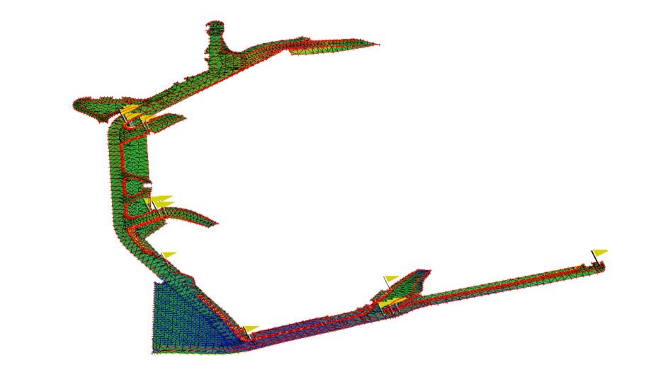
When you imported the PRO file, you got both a TIN Surface and the original 3D Points and Breaklines - they are all on the 01_ASB _ROADS layer. The TIN Model that is created from the PRO Surface that you imported is just that a TIN Model - to recreate that we treat it the same way that we treat a TIN from LandXML or TTM etc. i.e. that we create 3D Breaklines around each of the Triangle Faces so it faithfully reproduces the source TIN - but TINs cannot be edited in TBC - to create an Editable surface create a new surface from the Points, Breaklines and Boundary data on the 0_ASB_ROADS and Boundary Layers and the imported 3D Boundary will constrain the edge of the model as you want it - the only time that that could maybe fail is if there is a point outside the boundary or if a Breakline crosses outside the boundary making the Boundary void until you address the outlier or adjust the boundary to accommodate the outlier. In this case the Boundary appears to work fine. There are some Flags on the Surface where you have duplicate or crossing breaklines that likely need some attention - they are giving errors up to 5.5 cm in places - maybe not critical
Remember - TIN Models are not something we allow you to change inside TBC - you can make them editable if you export and re-import them using settings that convert the Triangles into 3D Faces (AutoCAD DWG Export of a TIN or a TTM Export can be re-imported as Points or 3D Faces. After re import, the 3D Faces can be deleted and then you can remake a surface from the 3D Faces that remain after editing. However in all cases, I would discard the TIN model and use the Points and Breaklines from the PRO to create my own surface based on the source data as that gives you all the control that you want inside TBC. To get the Import Settings you have to use the Import Command - select the Location and File and then based on the file type you will be given options to control how the imported data is converted and used in TBC (e.g. a 3D Faces file in DWG can come in as a TIN Model or as 3D Faces (which is at least editable - while not great it does match the source model) or in the case of a TTM as Points or as 3D Faces - while Points gives you data that you can create a controllable surface from, the source breaklines will not be available and therefore forming a model from Points only will not match the source model very well. The best way is to always transfer the source data and then to use TBC modeling engine to create the surfaces that you then have full control over inside TBC. Like in this case - your source TIN had boundary triangles that you don't want - and the TIN is not editable so you are stuck, but because you also had the source points and lines - you can create a model that is under your control. You could run a Cut Fill diff on the surface you create in TBC vs the surface created in Terramodel -however as you can see the Terramodel Surface has crossing Breaklines (the flags) that you will miss in Terramodel because it has no way to show you those crossing errors - so you are already able to create a better / more accurate model and fix up those errors in TBC that in Terramodel would have been errors that would always go undetected.
Here is a picture of the model I created from your data - boundary correctly applied
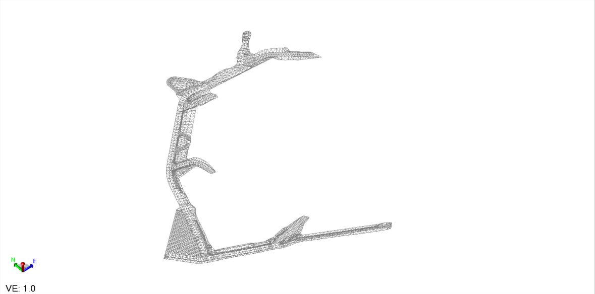
I exported the PRO generated TIN Model to AutoCAD DWG - that creates 3D Faces in the AutoCAD file - when you import that the 3D Faces are objects that you can select and delete - you cannot use Trim surface edge - but you can select and delete the edge triangles to get an edge that matches your boundary line - you can even use Select by Boundary and delete all the triangle faces that lie outside the boundary - once you have cleaned up the triangle faces you can then use those 3D faces and Boundary (not really needed in this scenario because all the triangle faces form a continuous breakline around the edge of the model anyway) to create a cleaned surface from the TIN only data if that is all you have to work with. Here is the result after editing (I just did a rough clean up job on this to show how it could be)
If you do the same with a TTM File - when you re-import it you can create Poly 3D objects (which are the same as 3D Faces and do the same job as above on the AutoCAD DWG 3D Faces
Hope this helps
Alan