I am not quite sure, what do you mean.
In fact, I defined for all different types of lines their specific layers and after that I did the line works.
So, every type of line has assigned its own specific layer.
When I joined them in one joined line, the joining procedure created one joined solid line.
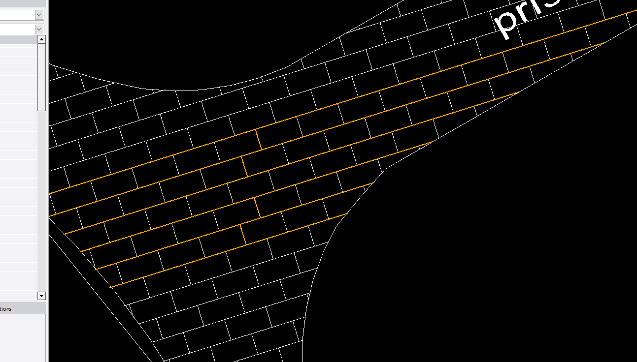
When I select (for example) the part of the joined line where the gate is (before joining) and change the line
on the type of line designed for gate - of coarse - all joined line changes from solid line for gate line type. When I break the joined
line in the place where the gate is, I lose the possibility for exploding, since there is no more closed shape.
By the way, why joining procedure selected the solid type of line for the joining and not - for example - line type
for fence or gate which are also parts of the segments to be joined?
Put into another words, I want to have a closed shape of the line for hatching in order to have the possibility to explode it,
whereas all its line parts should graphically retain their specific types of lines as designated before joining.
This is what I meant and what I wanted to achieve. So I do not understand what do you mean by using COPY/PASTE.
What should I copy and where should I paste it?
------------------------------
Martin Kalafut (Secondary email
------------------------------
Original Message:
Sent: 06-21-2022 03:51
From: Francisco Guerrero
Subject: Export of Hatching from TBC 5.70 to DWG
if you still have those original lines or have not saved that work. Just do a copy and paste of all those lines and save them on another layer such as "reference hatch lines". This way you keep the original lines as their specified line type.
------------------------------
Francisco Guerrero
------------------------------
Original Message:
Sent: 06-21-2022 01:05
From: Martin Kalafut (Secondary email
Subject: Export of Hatching from TBC 5.70 to DWG
Many thanks Francisco! I joined the corresponding lines and after hatching the required area I am able to explode it.
Still a question:
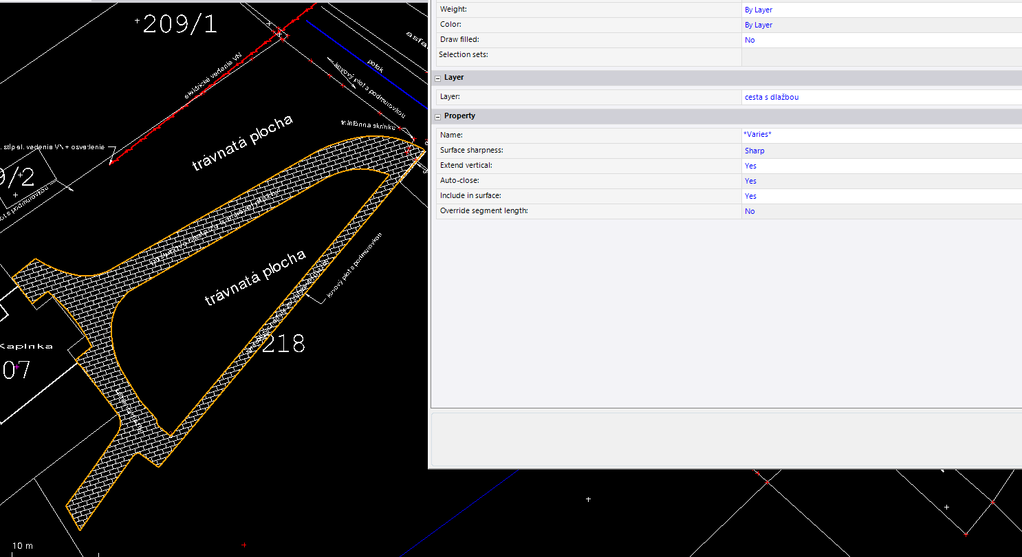
When I joined all corresponding lines to form a closed shape of the area for hatching, within joined
lines were different graphic types of lines (solid lines, fence line, gate line, etc. where some of them were graphically represented
with another than solid lines).
After such joining - the resulting one (joined) line is graphically represented as unified solid line. However, this is not
required result. I need to have some parts of the joined line to be graphically represented as they were before joining.
It means - part of the joined line would graphically represented by solid line, parts by a another types of lines (fence, gate, ...)
Is it possible to achieve it?
Martin
------------------------------
Martin Kalafut (Secondary email
Original Message:
Sent: 06-20-2022 14:36
From: Francisco Guerrero
Subject: Export of Hatching from TBC 5.70 to DWG
Hatch must be in a closed shape so it allows for explode to work. I connected the linework to create a boundary and then exploded the hatch which now works. either copy the linework or use those existing linestring to connect and close.
------------------------------
Francisco Guerrero
Original Message:
Sent: 06-20-2022 14:26
From: Martin Kalafut (Secondary email
Subject: Export of Hatching from TBC 5.70 to DWG
Here is my zipped vce file.
------------------------------
Martin Kalafut (Secondary email
Original Message:
Sent: 06-20-2022 14:14
From: Francisco Guerrero
Subject: Export of Hatching from TBC 5.70 to DWG
VCE. just the linework would work. upload on here.
------------------------------
Francisco Guerrero
Original Message:
Sent: 06-20-2022 14:08
From: Martin Kalafut (Secondary email
Subject: Export of Hatching from TBC 5.70 to DWG
Yes, no problem. What would you need - just vce file or also original GNSS RTK measurements?
Should I email it to you or post it here?
Just remember - I use a refined slovak coordinate system in my project as follows (which is NOT standard part of TBC installation):
But for this purpose, you can switch it to the standard part of the csd database - JTSK03 Krovak EN:
------------------------------
Martin Kalafut (Secondary email
Original Message:
Sent: 06-20-2022 13:41
From: Francisco Guerrero
Subject: Export of Hatching from TBC 5.70 to DWG
thats odd. I tried again on another project using 5.7 and I still am able to explode the hatch. mind sharing your work?
------------------------------
Francisco Guerrero
Original Message:
Sent: 06-20-2022 12:27
From: Martin Kalafut (Secondary email
Subject: Export of Hatching from TBC 5.70 to DWG
Look at my video attached:
------------------------------
Martin Kalafut (Secondary email
Original Message:
Sent: 06-20-2022 09:45
From: Francisco Guerrero
Subject: Export of Hatching from TBC 5.70 to DWG
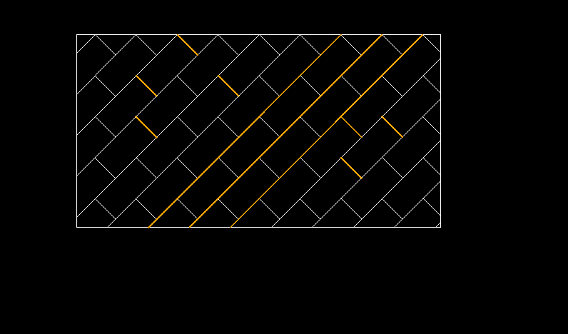
I was able to use the Explode command and explode the "hatch" into polyline segments.
I even exploded the block hatch
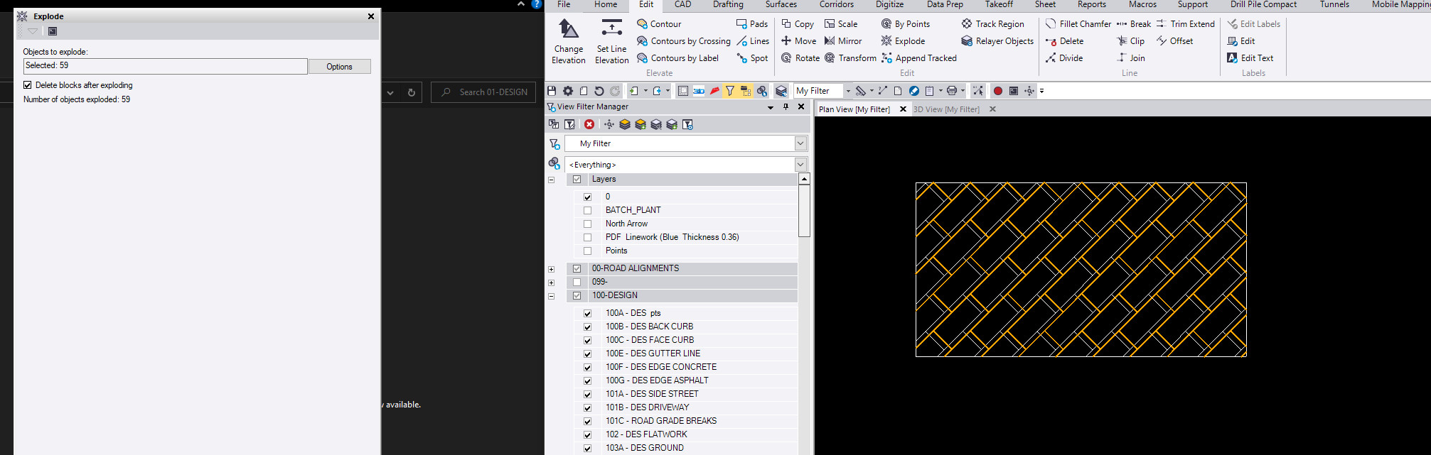
here I have selected some random segments after the explode.
------------------------------
Francisco Guerrero
Original Message:
Sent: 06-20-2022 02:27
From: Martin Kalafut (Secondary email
Subject: Export of Hatching from TBC 5.70 to DWG
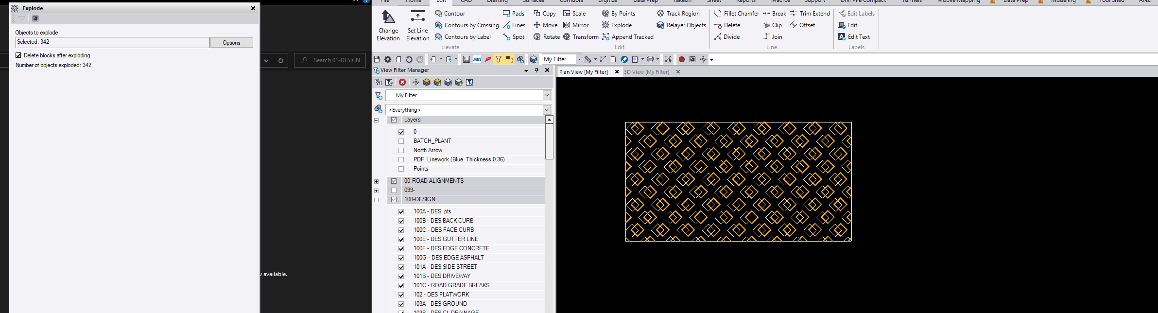
Francisco - maybe I do not understand it correctly but
I tried it, however it does not work. When I select the hatching itself to be exploded and explode it, then Number of objects exploded = 0.
(I used here the BLOCK pattern for hatching).
------------------------------
Martin Kalafut (Secondary email
Original Message:
Sent: 06-18-2022 19:49
From: Francisco Guerrero
Subject: Export of Hatching from TBC 5.70 to DWG
This is the case of micro and CAD not having that hatch pattern in their system. You could explode the hatch and then when imported used that exploded hatch to recreate the hatch in micro and CAD.
------------------------------
Francisco Guerrero