Trimble Business Center

 View Only
Expand all | Collapse all

Feature Coding for Control Codes in Access and Processing Feature Codes in TBC

  • 1.  Feature Coding for Control Codes in Access and Processing Feature Codes in TBC

    Posted 04-01-2019 10:58

    I had a question from a user this morning about how the Feature Coding in Access is used with the Process Feature Codes in TBC and how to solve a couple of issues relating to 


    1. Using 2 Point Blocks
    2. Using 3 Point Blocks
    3. Using Curve Fitting
    4. Using the Include in Surface Flag


    In the Answer you will find a short video and also some descriptions


    Alan


  • 2.  Re: Feature Coding for Control Codes in Access and Processing Feature Codes in TBC

    Posted 04-01-2019 16:43

    I will try to tackle these in sequence


    1) 2 Point Blocks are scaled by the distance between 2 measured points. You should ensure that your block is defined as a unit Length (X Axis) and whatever ratio you want the Y axis to be. So for example if I have a gate that will be drawn between two points coded GP (Gate Post) then I want my block to be 1 unit wide and maybe 0.2 units high. The below symbol is an example of a Gate Block.


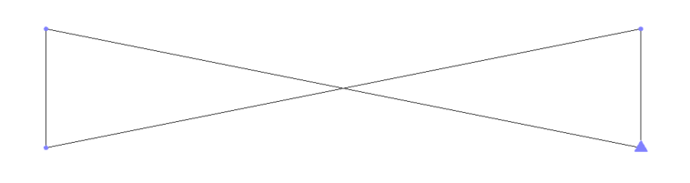
    If the two Gate Posts are 2.56m apart then the Block will be scaled by 2.61 - the Unit length X side will now be 2.61m long and the Y length will be 2.61 x 0.2m.


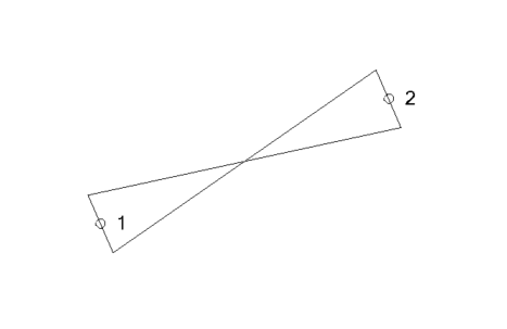
    2) 3 Point Blocks are scaled in X by the distance between points 1 and 2 of the measurements and the Y axis is scaled by the Perpendicular distance of point 3 from the line between points 1 and 2. The 3rd point can be e.g. measured anywhere on the side opposite the baseline (if e.g. a Rectangle like a Manhole) but also anywhere on the extended line of the opposite side if for any reason you cannot get to the opposite side (e.g. a car is parked over it etc.). Again the Block definition should be defined with Unit Length in both X and Y axes so that it can be scaled by the measurements made in the field. So if you have Manholes that are 0.6m x 0.4m your block should be a Square of 1m x 1m when you want to place it between 3 points.  The video shows how.


    Note: when you use 2 Point and 3 Point Blocks from measured data, it will find all the e.g. MH points in the file in sequence and group them into sets of three for this purpose. So if for some reason you measured an extra point somewhere in the survey with code MH, this will throw off all of your sets of three points - in Siteworks this doesn't happen as when you pick the code for a 3 point block, it automatically asks you to measure groups of three points, whereas in Access I don't believe it does that - I think you have to know to measure three point groupings and not make a mistake.


    3) Curve Fitting - the request that the customer made was to measure a series of points that fall on an Arc, however they also wanted to have a Gap in the Arc. I looked at the Line Control Codes and there is no "Gap" Line Control Code. There is a code that allows a point to be ignored in the processing of linework, however the linework will just join between the point prior and post the Ignored Point so this is not a Gap function. To add a Gap you need to End one line and start another based on what I could see in the Line Control Codes. So I create an END control code


    (used like KB END) 


    and that will stop a Line and allow it to be restarted using a code like KB. If the Gap between KB END and KB is on a curve, then you would need a Curve in the approach to the END point and a Curve starting from the KB point - however it will not use the Points KB END and KB over the Gap in the curve computation.


    The video shows how this works.


    4) Ignore Surface Flag - this puts a Flag on the measured Points of this type and sets the property of those objects during Feature Code Processing so that if at any point afterwards you add those points to a Surface Model they will be ignored in the model (The triangles will not connect to them). In TBC each point can be individually Added or Ignored in Surface Models through its Properties Pane. The Feature Coding in the Field is really targeting all points of this code to have the same property. So you could e.g. set all trees with code TR to be don't include in surface.  If you only want to ignore some trees then you would need two codes for Trees e.g. TR3D and TR2D where TR2D has the Ignore setting on the codes. For Line Features, since the Main Code can only be one value, I am not sure how you would exclude the Z value for a single point of many on a line through Field Coding - you would likely have to edit those in TBC after import and processing of feature codes


    Hope this is helpful


    Alan


  • 3.  Re: Feature Coding for Control Codes in Access and Processing Feature Codes in TBC

    Posted 04-02-2019 08:09

    Hi Alan,


    Thank you for your time.


    My understanding is that:
    1. I can not use controlo codes for lines or blocks with SCS900 and SiteWorks.
    2. There is no way to "no connect" a line between two points and keeping the curve passing the same points.


    At least now, I know that I am not missing anything on the process.


    Thank you very much,


  • 4.  Re: Feature Coding for Control Codes in Access and Processing Feature Codes in TBC

    Posted 04-02-2019 09:33

    You can enter control codes into SCS900 if you want to - when you import

    the SPJ File it uses the FXL file to process the data and it should just

    work- however SCS900 uses its own method for Curve Fitting so you would

    have to Not Use that if you want to use Control Codes. You would also have

    to type in all the code data and not use the Code List or Advanced Feature

    Code stuff that is available - so while this is not a "Designed Work Flow"

    all we deliver are Points With Codes and those codescan be manually entered

    and with the FXL file it will process them. You may need to run Process

    feature Codes to get that to work- I have never tried it but it should just

    work.


    Alan


    On Tue, Apr 2, 2019 at 9:09 AM fernando_catrau@trimble.com <


  • 5.  Re: Feature Coding for Control Codes in Access and Processing Feature Codes in TBC

    Posted 06-04-2019 23:09

    Hello Alan!


    Thanks for the video, very useful! Will definitely use this information about blocks control codes. 


  • 6.  RE: Re: Feature Coding for Control Codes in Access and Processing Feature Codes in TBC

    Posted 10-23-2022 06:36
    Hi Alan, in case you are still listening I wondered if you could help with this stumbling block.

    I have successfully used a 3 point block, a rectangle indicating a drainage manhole cover no less.  In my usual trusty ancient windows dos software I had the option to apply the mean level of 3 and only one set of txt / labels would appear. 

    There must be a way inside this far more advanced software surely? 

    Regards,


    ------------------------------
    Wayne Bainbridge
    ------------------------------


  • 7.  Re: Feature Coding for Control Codes in Access and Processing Feature Codes in TBC

    Posted 03-25-2020 05:10

    Thanks for the video Alan..VERY helpful.

    I have a extension to this question though.

    I am struggling to create the blocks for the 2 or 3 point feature codes.


    I am creating my blocks in CAD and importing them. I am getting the following error:


    I saw in your video that you created the block in TBC and added the insertion points there. How do I import the CAD linework into TBC, so that I can create the block in TBC. I have some complicated blocks and do not want to just redraw them in TBC.


  • 8.  Re: Feature Coding for Control Codes in Access and Processing Feature Codes in TBC

    Posted 03-25-2020 06:39

    In TBC we actually use AutoCAD Blocks behind the scenes so you can Import the Blocks as a DWG, then create an instance of the Block using Insert Block and then Explode the Blocks using the Explode Command - or you can Explode instances of the Blocks in AutoCAD and then export the linework etc as a DWG and import that into TBC. Once you have the linework in TBC then use the Create Block command to create the Block and in that process you can define them as 1, 2 or 3 point blocks which is a little unique compared to AutoCAD.


    Alan


  • 9.  Re: Feature Coding for Control Codes in Access and Processing Feature Codes in TBC

    Posted 03-25-2020 06:40

    If you send me your file I can take a look and record you a video. Agree that the message you are getting is not easy to determine what is going wrong.


    Alan


  • 10.  RE: Re: Feature Coding for Control Codes in Access and Processing Feature Codes in TBC

    Posted 01-19-2021 00:51
    Edited by Anouk KIEFFER 01-19-2021 02:46
    Hi Alan,

    I think you have the answers i'm looking for, but the video you mention seams not available anymore, i can see pictures but no video...
    I would like to use 3 Points blocks (for rectangle manhole cover for example)

    I made this :


    So i first created my block on TBC, with 3 insertions points, and export in dwg.
    Then, on Feature Definition Manager, i've imported the block. I choosed insertion "with 3 points". I saved my work and sent the fxl file on my Trimble T7 tablet.
    I'm using Trimble Siteworks. I tried to use my "L1T" Code but it create a line. I tried to raise 3 points to see what happen on TBC, but my block doesn't appears. On TBC, I've imported my fxl file, then the spj file from work order. The lines appear, the symbols assigned to one point appear, but the blocks doesn't. I guess i'm missing something... 


  • 11.  RE: Feature Coding for Control Codes in Access and Processing Feature Codes in TBC

    Posted 03-29-2023 11:59

    Hi Alan et al, 

    new member here.

    I'm trying to add some features in TBC and am having issues.

    Basically I'm trying to add AutoCAD blocks with either a single or multiple insertion points. Such as an arrow on a road with start and point of arrow to be the points to record and for an arrow to scale created.

    I appear to be having issues, as per another user below, where there is an issue with any number of insertion points selected?

    Another issue is that my Point and AutoCAD block are not aligned, with some distance between recorded point and block?

    Not sure where I've gone wrong and how to correct it.

    Any advice would be greatly welcomed.


    ------------------------------
    Nick Jackson
    ------------------------------


  • 12.  RE: Feature Coding for Control Codes in Access and Processing Feature Codes in TBC

    Posted 03-30-2023 06:45

    Hi Nick,


    I know that Trimble Access does not display blocks.  Anything from AutoCAD (typically exported as a DXF), that I want to see as linework in Access, I have to explode first.  You might try that in TBC before inserting.  In AutoCAD, dimensions, leaders, and arrows are considered blocks.


    Please let us know if you figure it out.


    Best Regards,


    Brian C