Trimble Business Center

 View Only
Expand all | Collapse all

Vertical Design from CSV file or AutoCAD or Profile view

  • 1.  Vertical Design from CSV file or AutoCAD or Profile view

    Posted 12-30-2022 01:40
      |   view attached
    I have a surface in TBC.

    I intend to create a profile on a line (Polyline) and use the profile generated by TBC as the VAL of the corresponding alignment. How do I go about it.

    I have created a CSV fie (attached - Stn #, Station, Offset, Elevation, Code) providing the Station and Elevations. Want to import this file in profile view and use the profile as the VAL for the corresponding alignment.

    I have a profile generated in AutoCAD. Want to import that as the VAL for the corresponding alignment in TBC.

    How do I go about each of them.

    Many thanks for all help.​

    ------------------------------
    Saif Bin Darwish
    ------------------------------

    Attachment(s)

    csv
    CL-RGL.csv   72 KB 1 version


  • 2.  RE: Vertical Design from CSV file or AutoCAD or Profile view

    Posted 01-04-2023 06:06
    I assume you know that you can create an Alignment from any Linestring

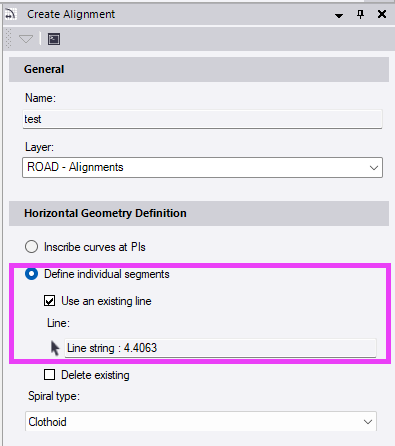
    But you'll need to have the linestring ready with at least a horizontal definition.

    For your CSV file you need to have an Alignment with at least the horizontal component ready.
    If you have multiple alignments in your project the CSV filename must match the name of the target alignment.

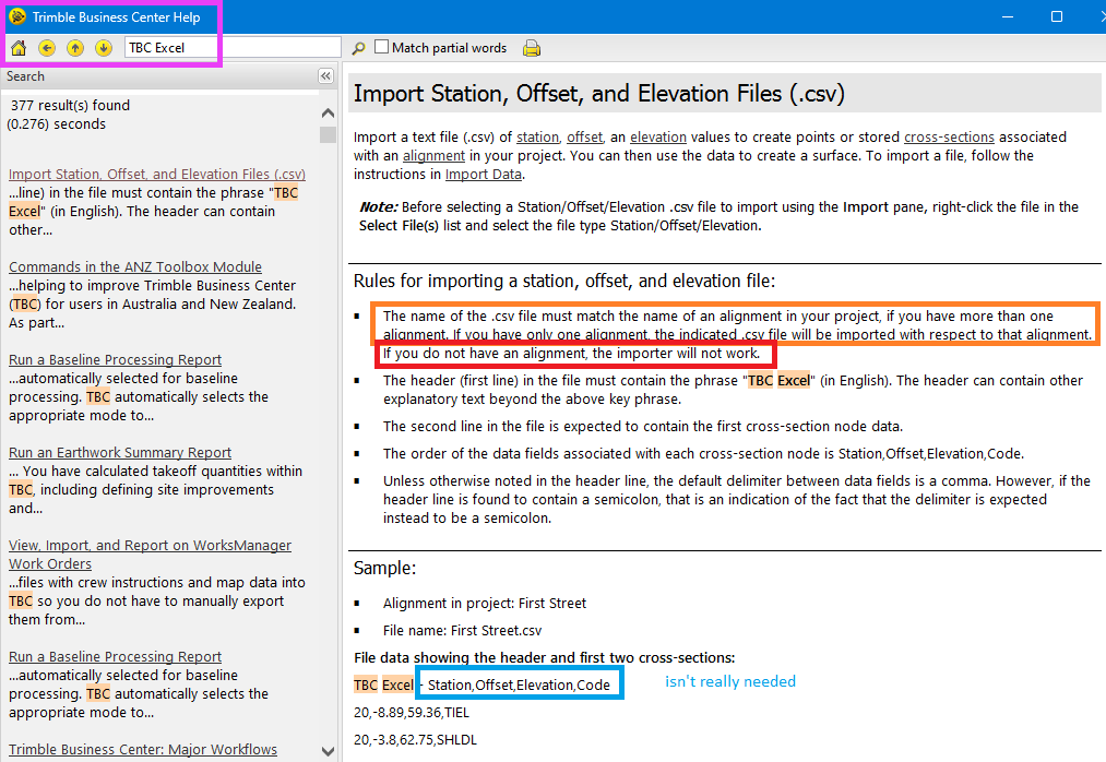
    In your CSV file you need to get rid of the Column 1 with the point numbers and the last 2 columns. It must be 3 or 4 columns maximum.
    If you have successfully imported your file, you'll end up with "Stored Cross Section Nodes" along the alignment
    - select one of them
    - right click -> Select Similar
    - CAD-Tab -> Explode
    - now you have single string lines and points in addition to those cross sections
    - select one of the small stringlines
    - right click -> Select Similar
    - CAD-Tab -> Join

    As long as I know is there no way to combine a given horizontal alignment with another vertical alignment. Or as you asked an imported 2D profile drawing.
    So, I did some programming the last few days. The attached macro will do the following:
    • lets you combine the horizontal component of one line (Line 1) with the vertical profile of another (Line 2)
    • the vertical profile can also be a 2D-Line in Planview, in that case you'll have to define the origin (Chainage 0.0 and Elevation 0.0; Chainage-Axis parallel to Easting and Elevation-Axis parallel to Northing)
    • in case the length of Line 1 doesn't match the length of Line 2 you can compute the Scale to stretch/shrink it accordingly
    • the vertical scale will work independently of the horizontal scale
    • you can also draw the vertical profile to the plan view (with variable scales and direction)
    • in either case, if a scale other than 1.0 is applied the macro needs to chord the profile first, otherwise any curvature in the profile would get messed up (you can't simply stretch arcs and splines); it will use the bigger one of the scales to recalculate the chording tolerances
    • the resulting line will always be a linestring, just create a new alignment from it
    See the attached video for a demonstration.


    Unzip the macro ZIP into a folder in "C:\ProgramData\Trimble\MacroCommands" and restart TBC.

    ------------------------------
    Ronny Schneider
    ------------------------------

    Attachment(s)

    csv
    Works.csv   34 KB 1 version
    zip
    SCR_MergeLineProfile.zip   10 KB 1 version


  • 3.  RE: Vertical Design from CSV file or AutoCAD or Profile view

    Posted 01-04-2023 06:14
    Edited by Ronny Schneider 01-04-2023 17:47
    And you can drape any linestring with standard TBC function onto a surface.


    ------------------------------
    Ronny Schneider
    ------------------------------


  • 4.  RE: Vertical Design from CSV file or AutoCAD or Profile view

    Posted 01-04-2023 22:22
    Please see my *.csv file. I suppose this format is OK. I was expecting to change file type to "Station, Offset, Elevation".

    Did not find. (Please see attached images).

    Can you please help me find a solution thanks.

    I would be happy also to learn how I can generate XS and Quantities between any two of three surfaces in this project with this Center Line.

    Thanks.
    The information transmitted through this mail is confidential and may be legally privileged. Access to this mail other than the intended recipient is unauthorized. If you are not the intended recipient, please notify us or erase contents. Any re-transmission, dissemination, action or omission based on the content of this mail by persons other than the intended recipient may be unlawful and strictly prohibited. We monitor email communications through our network. Any violation for the above norms may lead to prosecution.


    Attachment(s)

    csv
    VAL-CL-RGL.csv   36 KB 1 version