If you don't have any custom macros or your TBC licence is one of the low tier ones you can convert the string to alignment, then create a corridor, then generate a dummy template (eg. Centre line and 1m offset) and then set the corridor setting to generate cross-section every 1m.
you will get a surface, explode it and remove that dummy string.
you will be left with a string that is a generalisation of your original strings, but this time with vertices every 1.0m
------------------------------
Marian
------------------------------
Original Message:
Sent: 04-12-2023 00:18
From: Luboš Bejček
Subject: what is wrong for this CAD line for earthwork report ??
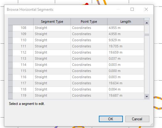
So ....generaly....the problem could be zero lenght segments and too small segments..... what is the smallest lenght for TBC that alow compute the report?......
What can you advice to us that dont have Project Clean up?....
------------------------------
Luboš Bejček
------------------------------
Original Message:
Sent: 04-11-2023 14:10
From: Ronny Schneider
Subject: what is wrong for this CAD line for earthwork report ??
There were still too small line segments.
I've run both through Project Cleanup and now the earthworks report computes.
------------------------------
Ronny Schneider
Original Message:
Sent: 04-11-2023 02:43
From: Luboš Bejček
Subject: what is wrong for this CAD line for earthwork report ??
Thank you.
This is the first time I´ve met this problem. It is a pitty I have not licenced the Clean up in Data prep so as ANZ.
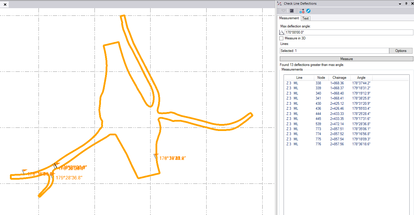
I edited this line to get out the wrong geometry and made another two lines from it. Now the geometry check in CAD doesnt show any flags/problems so it should be clean....but the earthwork report is still only zeroes
I cant find a way how to add an attachment in this reply...
https://drive.google.com/drive/folders/1jhER5u4UIvuaeVxyHAMskTA6AzIeBY2v?usp=share_link
------------------------------
Luboš Bejček
Original Message:
Sent: 04-10-2023 20:27
From: WorksOS SWC
Subject: what is wrong for this CAD line for earthwork report ??
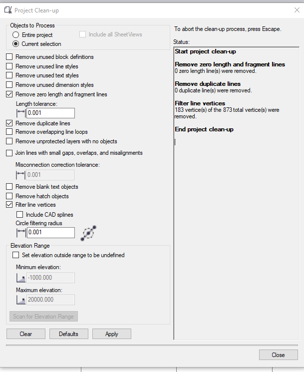
Earthworks report requires lines with "clean" geometry.
Your line has zero length segments and it overlaps itself. 20% can be safely removed.
CAD -> Data -> Detect Crossing Geometry
Data Prep -> Project Cleanup
ANZ Edit -> Check Deflections
------------------------------
WorksOS SWC